
Continuous, complete, automatic, non-leaking, non-aerating, positive pressure one-piece vent and pouring combination utilizing one direct venting aperture

a technology of direct venting and pouring combination, which is applied in the direction of liquid flow controllers, teats, packaging, etc., can solve the problems of consumer rejection, other unfavorable chemical reactions, and the quality of wine is deteriorated, so as to achieve rapid and efficient liquid removal

Inactive Publication Date: 2011-09-29
BROWN CRAIG E +1
View PDF37 Cites 19 Cited by
  • Summary
  • Abstract
  • Description
  • Claims
  • Application Information

AI Technical Summary

Benefits of technology

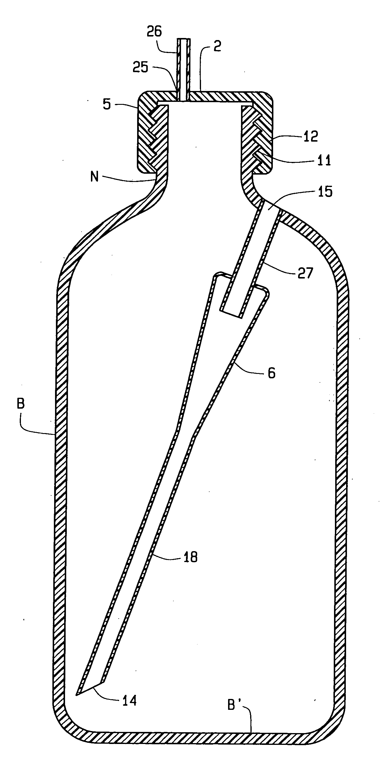
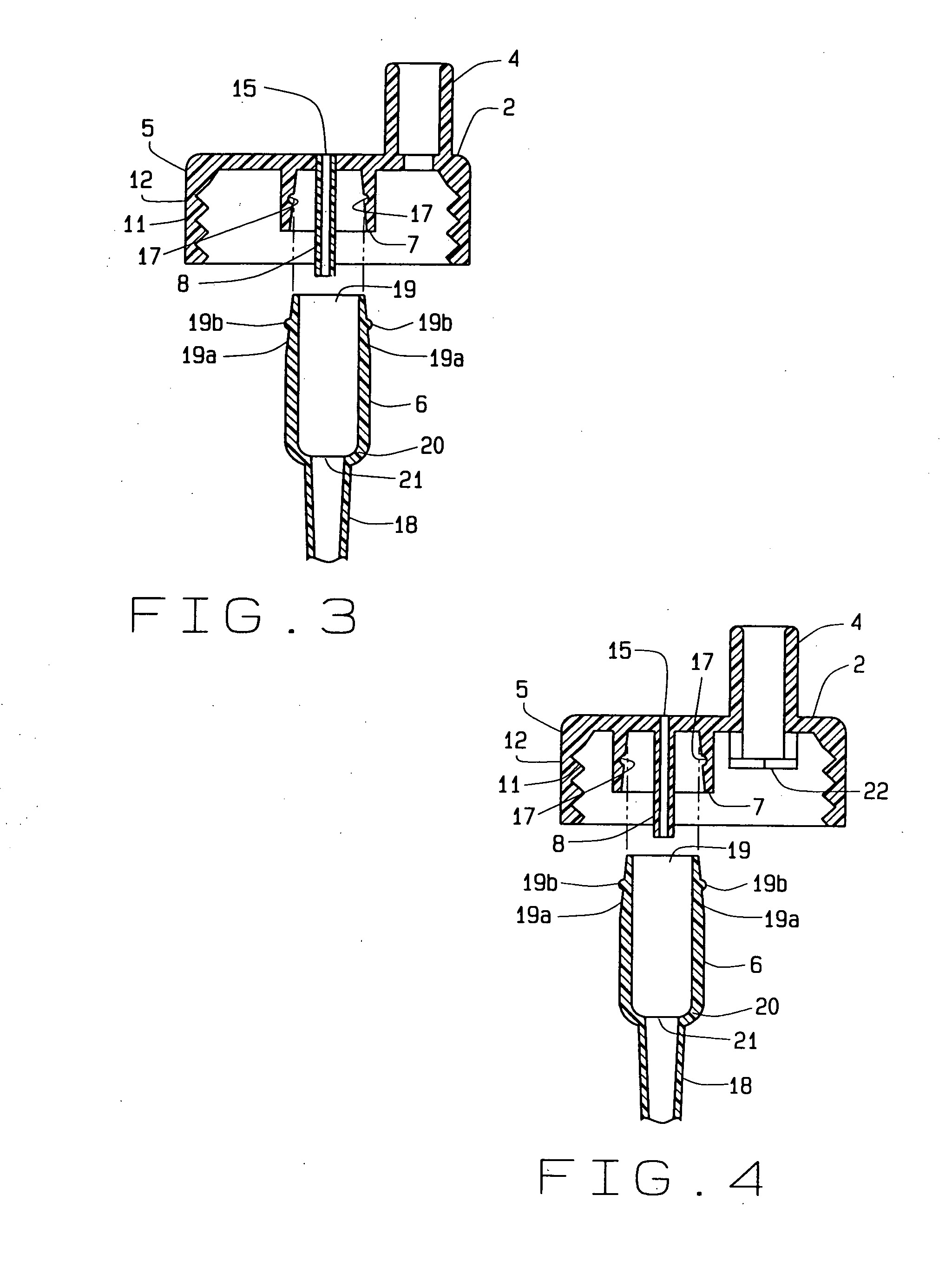
[0013]The preferred embodiment of this invention consists of only one additional part, a reservoir and its extension, which is attached to a container and its closure. The invention may consist of the reservoir with its extension; the closure and the reservoir with its extension; or, alternatively, the container, the closure, and reservoir with its extension. The reservoir is typically larger than the extension and the extension is typically conical and larger superiorly. An internal venting tube, which is molded as an extension of the closure, has its superior aspect open to the outside ambient air and its inferior aspect open to the volumetric center of the reservoir, thereby providing double venting. The internal venting tube eliminates the need for an additional component for the flow of air, which is unique to this invention. Previously, the internal venting tube, which required the attachment of another component for functioning, is now a component of the closure, thereby eliminating the need for attachment of another component for proper functioning.
[0080]Another object of the invention is to provide more attachments to the superior aspect of a container or closure utilizing continuous, complete, automatic, non-leaking, non-aerating, positive pressure one-piece vent and pouring combination utilizing one direct venting aperture such that the container contents exit onto any desirable surface that assists in feeding or any other purpose. One example is that an item such as a spoon may be attached to the end superior aspect of the container, and the contents of the container may be deposited on the spoon and then consumed.

Problems solved by technology

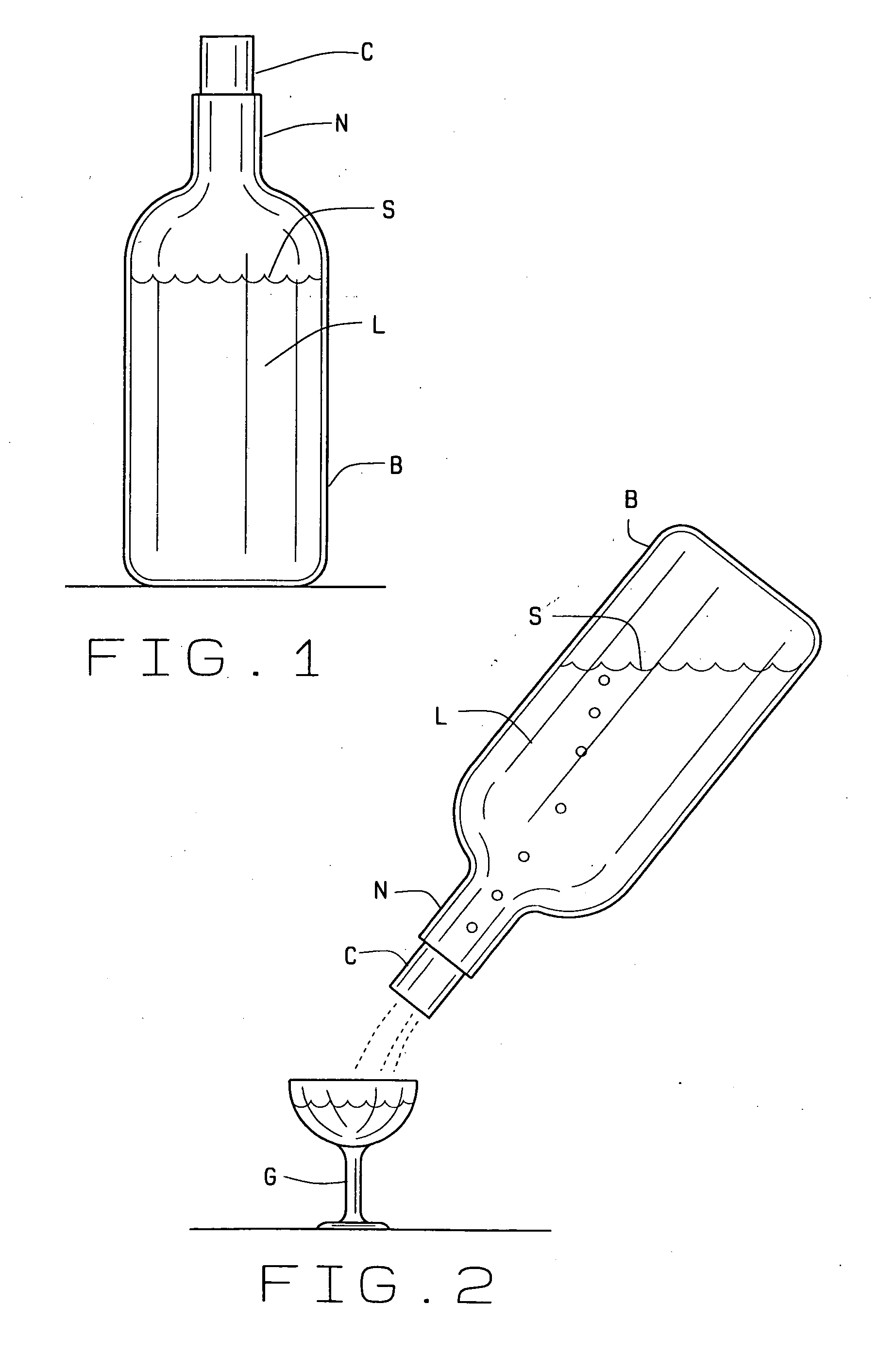
Any air that also mixes into the liquid is another untoward outcome of pouring that occurs from prior art containers.
But, oxidation of many of the ingredients of wine may occur and diminish the quality of the wine, possibly to the point of consumer rejection.
Other unfavorable chemical reactions occur due to the introduction of air into other conventional containers of liquid, such as cola, including the introduction of other airborne chemicals, pollutants, particulates, and the like that may co-contaminate the liquid.
Unfortunately, these unfavorable reactions occur repeatedly to the remaining liquid in a conventional container with each pour.
The undesirable effects increase many times over as air is frequently reintroduced, with continuing contamination of the liquid.
Prior art containers that hold and pour liquids and have disadvantages such as leaking, introducing air into the liquid, not pouring on demand, not venting the container, not providing a positive pressure inside the container, and utilizing more than one component to the vent.
If the vent is not oriented correctly, a significant amount of liquid is spilled from the vent to the outside of the container and typically onto the user of the container.
Prior art containers may leak because of container or container component compression in any container direction.
Containers may increasingly leak from an increasing amount of pressure on the container or its components and increasing dispenser size.
Prior art containers also suffer a prolonged lack of venting due to the capillary action of a small vent tube and may trigger a partial vacuum.
Further, over tightening of a collar upon an existing container leads to a complete vacuum.
Also, prior art containers may trigger the occurrence of negative pressure in the container.
Some of the prior art containers utilize a check valve to slow or prevent liquid from leaking from the container, but a negative pressure must form in the container in order for the valve to open, which introduces other negative effects.
Prior art containers also prevent the beneficial effect of formation of positive pressure formation in the container.
During pouring from a prior art container, the path of the liquid stream frequently becomes erratic, thereby making measurement of the liquid dispensed difficult.
Prior art containers, especially those of glass, are more difficult to manufacture.
However, a reservoir with an attached ring becomes impossible to insert into any size container because the ring centers the reservoir in the center of the neck, preventing insertion of the small vent tube into the neck of the container.
Tightening the closure too tightly on many prior art containers seals the vent closed, making it inoperable.
Further, improper sealing at the closure then may lead to leakage outside the container.
A fair number of prior art containers cannot be completely disassembled, which prevents cleaning and results in bacterial buildup and residue, and therefore prevents reuse.
Prior art containers also take few steps to prevent the problems associated with air blending with the liquids in the containers Alas, prior art containers alter the quality of liquid product contained therein as air enters the liquid.
Each usage of a prior art container brings in a volume of air that leads to oxidation and other contamination of liquid.
These changes may accumulate and adversely affect the value of the liquid, leading ultimately to its removal from store shelves.
During pouring from prior art containers, liquid within the venting tube may frequently leak from the container.
In using prior art containers, the users often do not have the desired rate of pouring of liquid out of the container and also do not have an even rate of pouring of liquid.
Also, one version of a prior art vent U.S. Pat. No. 3,168,221 to Parker, which is slightly smaller than the pouring spout, is cylindrical and extends from the outside of the container to the bottom of the container, and leaks a significant amount of fluid from the vent when poured, due to the lack of a significant air pressure stream in the vent to propel the liquid in the air vent back into the container before it leaks to the exterior of the container.
In all of the versions of the patent to Parker, contamination of the liquid by the air entering the container occurs, and no desirable positive pressure is present in the container at the onset of pouring.

Method used


Image

  • Continuous, complete, automatic, non-leaking, non-aerating, positive pressure one-piece vent and pouring combination utilizing one direct venting aperture
  • Continuous, complete, automatic, non-leaking, non-aerating, positive pressure one-piece vent and pouring combination utilizing one direct venting aperture
  • Continuous, complete, automatic, non-leaking, non-aerating, positive pressure one-piece vent and pouring combination utilizing one direct venting aperture

Examples


Embodiment Construction

[0124]The present invention overcomes the prior art by providing a venting tube enabling return of any liquid in the venting tube back into the container without leakage out of the container. The present invention provides a vent to overcome the disadvantages of the prior art by providing a liquid aperture, an air aperture, and a venting mechanism of various shapes and proportions to simultaneously vent a container and prevent leakage from the container while utilizing a preferably conical mechanism and utilizing only one additional part to the container and closure. Additionally, double venting and a reservoir are utilized.

[0125]Another embodiment of the present invention overcomes the prior art limitations by providing a closure, venting, and related components that fit on or within the neck of a liquid container, such as a wine bottle, sports bottle, or other container, and minimizes the mixing of air with liquid not yet poured from the container while eliminating spillage from t...


PUM


Abstract

A vent prevents a vacuum within an inverted container of liquid and eliminates components found in other container vents. The vent utilizes a conical or other shaped venting tube extending from the closure or a reservoir with reservoir extension and an air conduit extending inferiorly from a closure. The closure is either a leak resistant or leak proof seal. The superior aspect of the reservoir contains an inferiorly projecting air conduit, opening at the volumetric center of the reservoir. The reservoir extension projects distally into the container to reach the inferior aspect of the container. The vent provides an airway between the outside and the interior of the container so air freely passes to the distal aspect of the container without contaminating the liquid. Any liquid within the reservoir extension then collects in the reservoir during inversion of the container and then returns to the container when upright. Various attachments may be associated with the container, such as a nipple or spoon for infant feeding.

Description

CROSS REFERENCE TO RELATED APPLICATION[0001]This non provisional application claims priority to the application No. 61 / 340,993, filed Mar. 25, 2010, which claims priority to the to the pending non-provisional application Ser. No. 12 / 321,455 which was filed on Jan. 21, 2009 and which claims priority to the provisional application 61 / 062,754 which was filed on Jan. 29, 2008, which claims priority to the pending non-provisional application Ser. No. 12 / 321,439 which was filed on Jan. 21, 2009 and which claims priority to the provisional application 61 / 062,817 which was filed on Jan. 29, 2008, to the pending PCT application Serial No. US2009 / 000133 which was filed on Jan. 9, 2009 designating the U.S., which claims priority to the pending non-provisional application Ser. No. 12 / 291,749 which was filed on Nov. 18, 2008, which claims priority to the provisional application 61 / 003,635 which was filed on Nov. 19, 2007, to the pending non-provisional application ser. No. 12 / 072,465 which was f...

Claims


Application Information

Patent Timeline
Patent Type & Authority Applications(United States)
IPC IPC(8): B67D3/00
CPCA47G19/2266B65D47/32A61J11/04A61J11/02B65D47/06B65D47/2018
Inventor BROWN, CRAIG E.BROWN, ROBERT J.
Owner BROWN CRAIG E
Learn More