Aquifer-based hydroelectric generation

a hydroelectric generation and aquifer technology, applied in the direction of electric generator control, sewer pipelines, machines/engines, etc., can solve the problem that the system does not include any pumps to move fluid, and achieve the effect of reducing the amount of greenhouse gas produced, low cost, and affordable ra

Inactive Publication Date: 2011-09-29
RILEY WILLIAM
View PDF45 Cites 12 Cited by
  • Summary
  • Abstract
  • Description
  • Claims
  • Application Information

AI Technical Summary

Benefits of technology

[0024]For example, hydroelectric generating systems may be created at a relatively low cost. Accordingly, the resulting hydroelectric energy may be provided to end users at a more affordable rate. Moreover, electrical energy can be produced in a very clean, environmentally-friendly manner. The techniques disclosed herein can help reduce the amount of greenhouse gas produced in generating electrical energy.

Problems solved by technology

However, the system does not include any pumps to move fluid from the aquifer to the source of fluid.

Method used


Image

  • Aquifer-based hydroelectric generation
  • Aquifer-based hydroelectric generation
  • Aquifer-based hydroelectric generation

Examples


Embodiment Construction

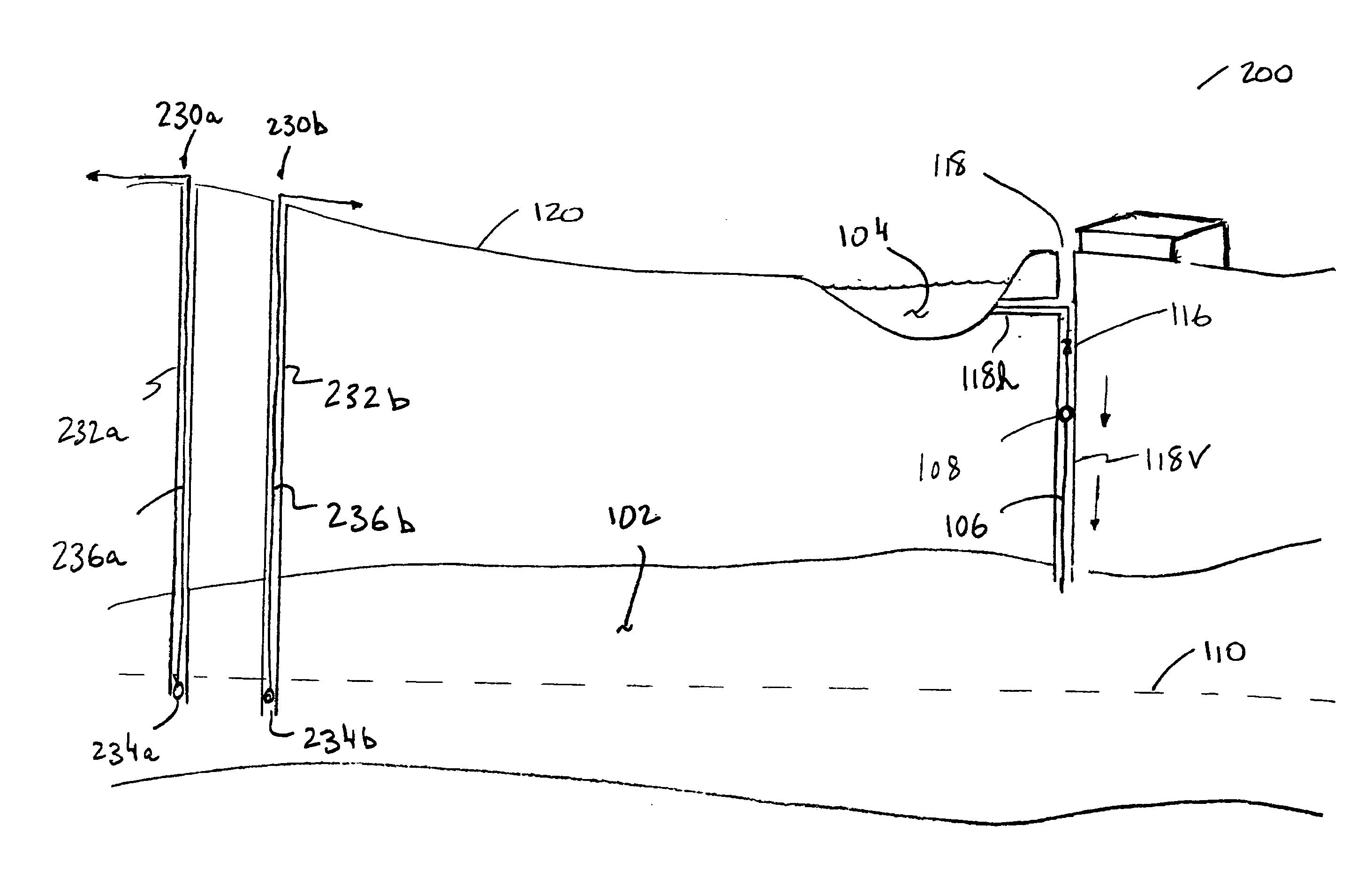
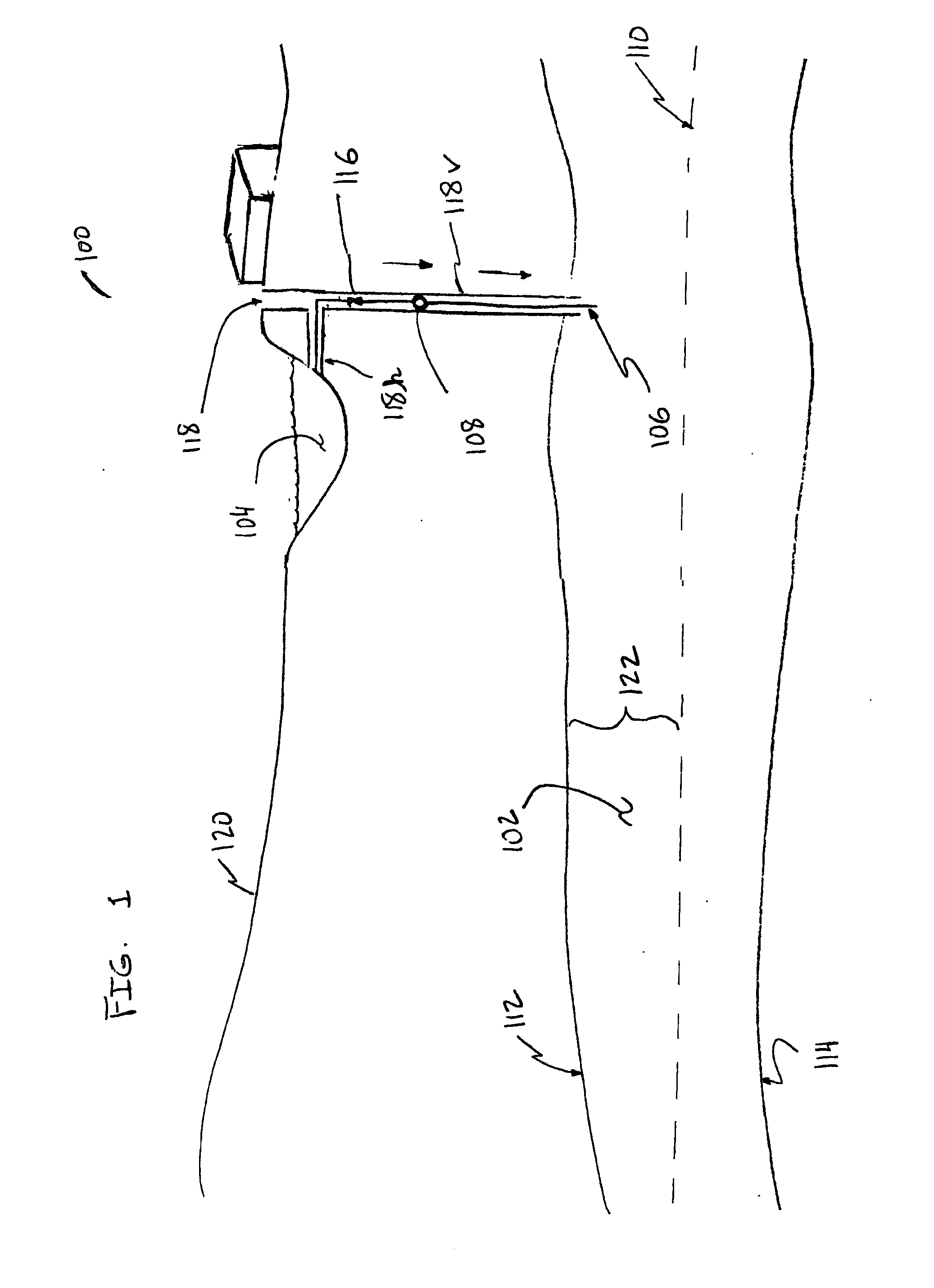
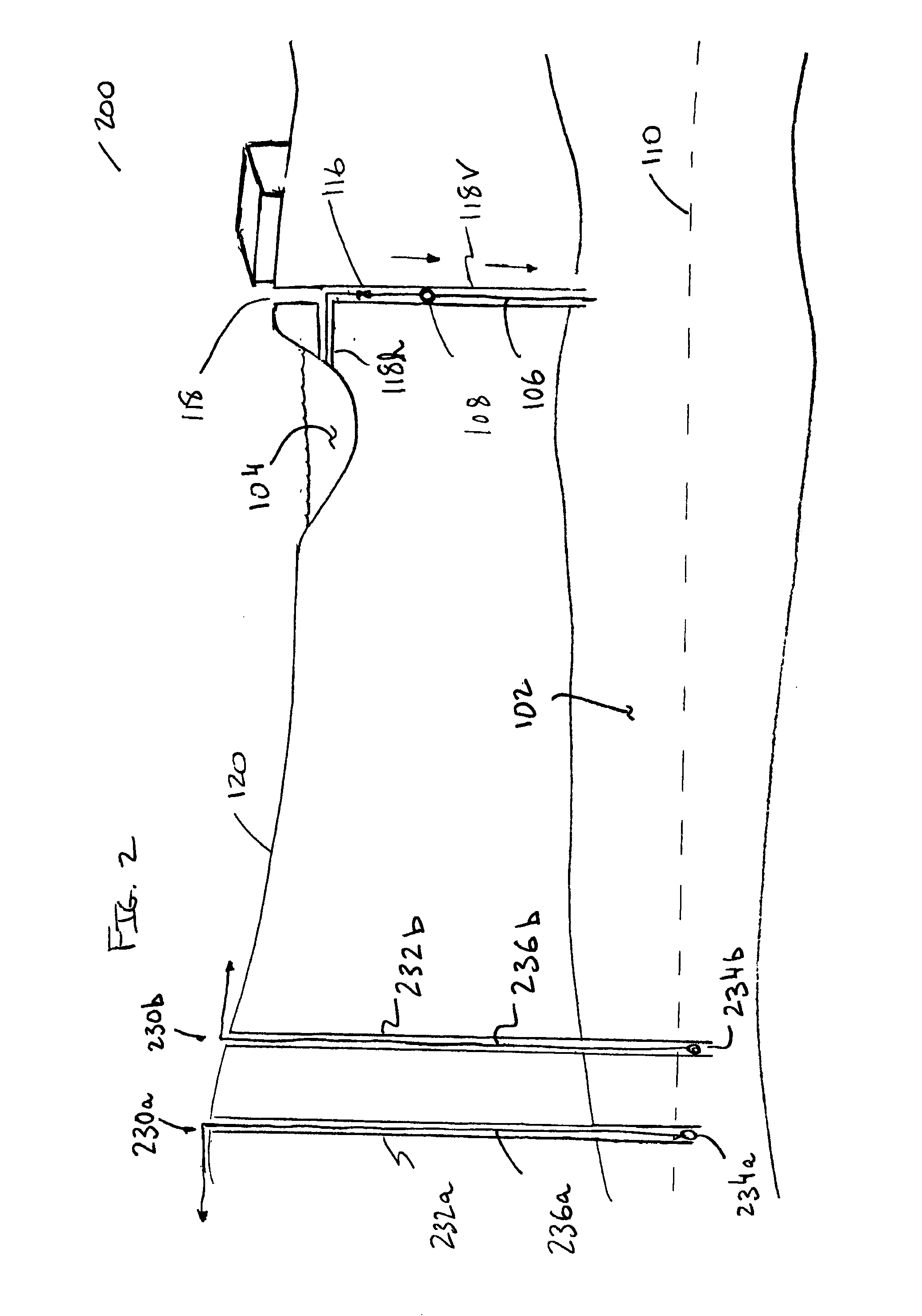
[0033]FIG. 1 is a schematic diagram of a system 100 that includes an aquifer 102 and an external source of fluid 104, which, in the illustrated example, is a lake at a higher elevation than the aquifer 102. A fluid communication channel 106 extends between the lake 104 and the aquifer 102. An engine-generator (e.g., a water turbine-generator 108) is arranged to convert the kinetic energy of fluid flowing through the fluid communication channel 106 from the lake 104 to the aquifer 102 into electrical energy.

[0034]In the illustrated system 100, the aquifer 102 is able to receive fluid from the lake 104. There are a variety of ways that an aquifer can have the ability to receive fluid from an external source, such as the lake 104. For example, the aquifer could be partially or completely depleted and, therefore, have a substantially fluid-free space inside the aquifer to store additional fluid. Aquifers can become depleted, for example, by being pumped or by virtue of fluid evaporating...


PUM

PropertyMeasurementUnit
energyaaaaaaaaaa
electrical energyaaaaaaaaaa
gravityaaaaaaaaaa

Abstract

A system includes an aquifer and a source of fluid external to the aquifer. A fluid communication channel extends between the source of fluid and the aquifer. Fluid can flow from the source of fluid to the aquifer through the fluid communication channel. An engine-generator is arranged to convert energy of the flowing fluid into electrical energy. No pumps are provided to move fluid from the aquifer to the source of fluid.

Description

FIELD OF THE INVENTION[0001]The present application relates to hydroelectric generation and, more particularly, to aquifer-based hydroelectric generation.BACKGROUND[0002]Hydroelectric generation involves utilizing flowing fluid (e.g., water) to produce electrical energy (e.g., electricity. A large portion of the world's hydroelectric energy comes from dammed water driving a water turbine and generator.[0003]Aquifers are naturally-occurring layers of permeable rock or unconsolidated materials that are capable of bearing fluid or do bear fluid.SUMMARY OF THE INVENTION[0004]In one aspect, a system includes an aquifer and a source of fluid external to the aquifer. A fluid communication channel extends between the source of fluid and the aquifer. Fluid can flow from the source of fluid to the aquifer through the fluid communication channel. An engine-generator is arranged to convert energy of the flowing fluid into electrical energy. However, the system does not include any pumps to move...

Claims


Application Information

Patent Timeline
Patent Type & Authority Applications(United States)
IPC IPC(8): F03B13/08C02F1/00
CPCF03B13/06Y02E60/17Y02E10/22F03B13/08Y02E10/20Y02E60/16
Inventor RILEY, WILLIAM
Owner RILEY WILLIAM
Why Eureka
Try Eureka