Apparatus for detecting displacement of electromagnetic actuator

a technology for electromagnetic actuators and actuators, applied in the direction of magnets, magnetic bodies, instruments, etc., can solve the problems of difficult to ensure the installation space of differential transformers, requires expensive strain gauges or optical sensors, etc., and achieves compact structure, high degree of design freedom, and simplified structure.

Active Publication Date: 2011-09-29
YAMAHA CORP
View PDF7 Cites 31 Cited by
  • Summary
  • Abstract
  • Description
  • Claims
  • Application Information

AI Technical Summary

Benefits of technology

[0023]According to the apparatus constructed as described above, the electromagnetic actuator has a simplified structure obtained by adding the detect...

Problems solved by technology

The disclosed apparatus, however, requires an expensive strain gauge or optical sensor.
It is, however, ...

Method used


Image

  • Apparatus for detecting displacement of electromagnetic actuator
  • Apparatus for detecting displacement of electromagnetic actuator
  • Apparatus for detecting displacement of electromagnetic actuator

Examples


Embodiment Construction

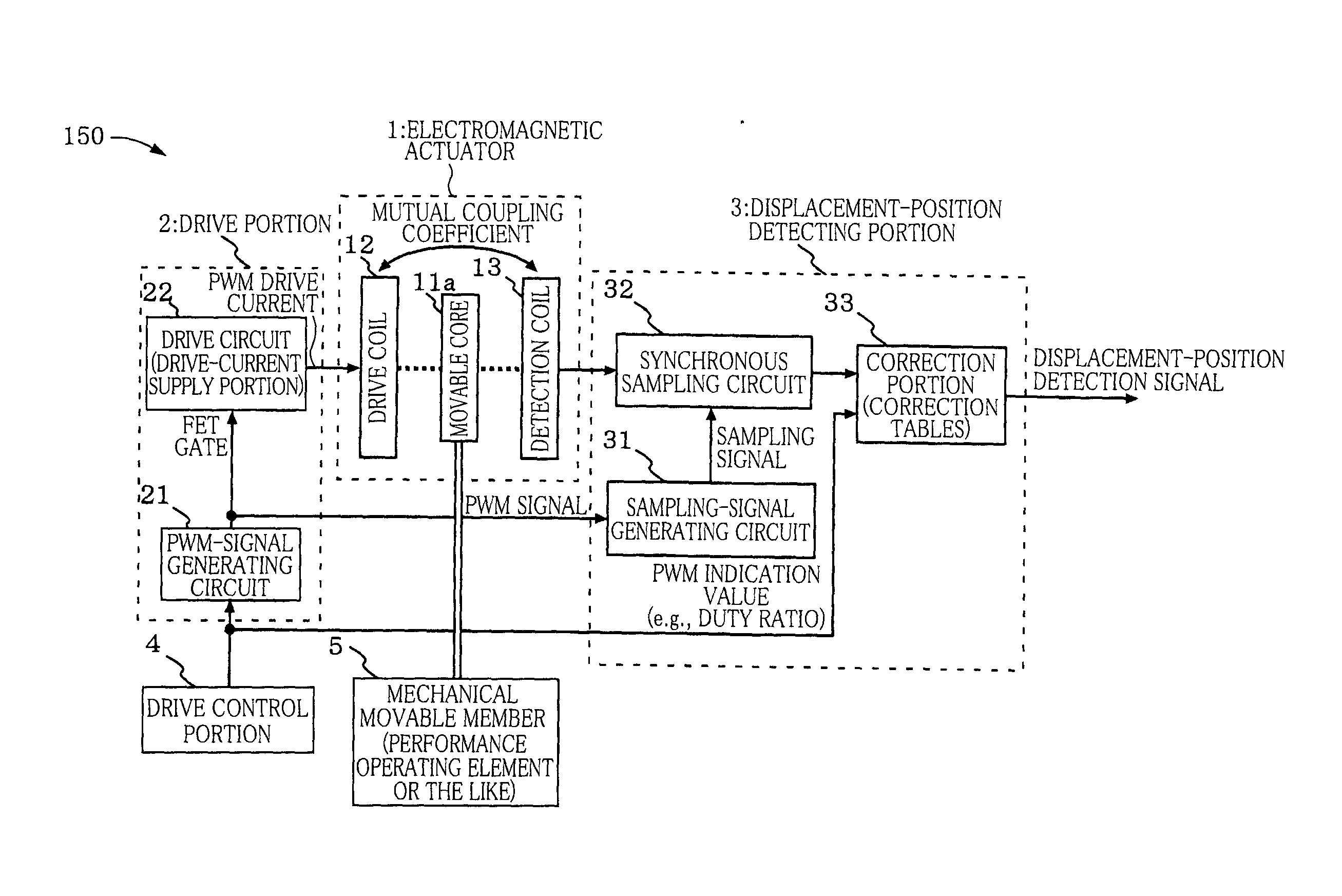
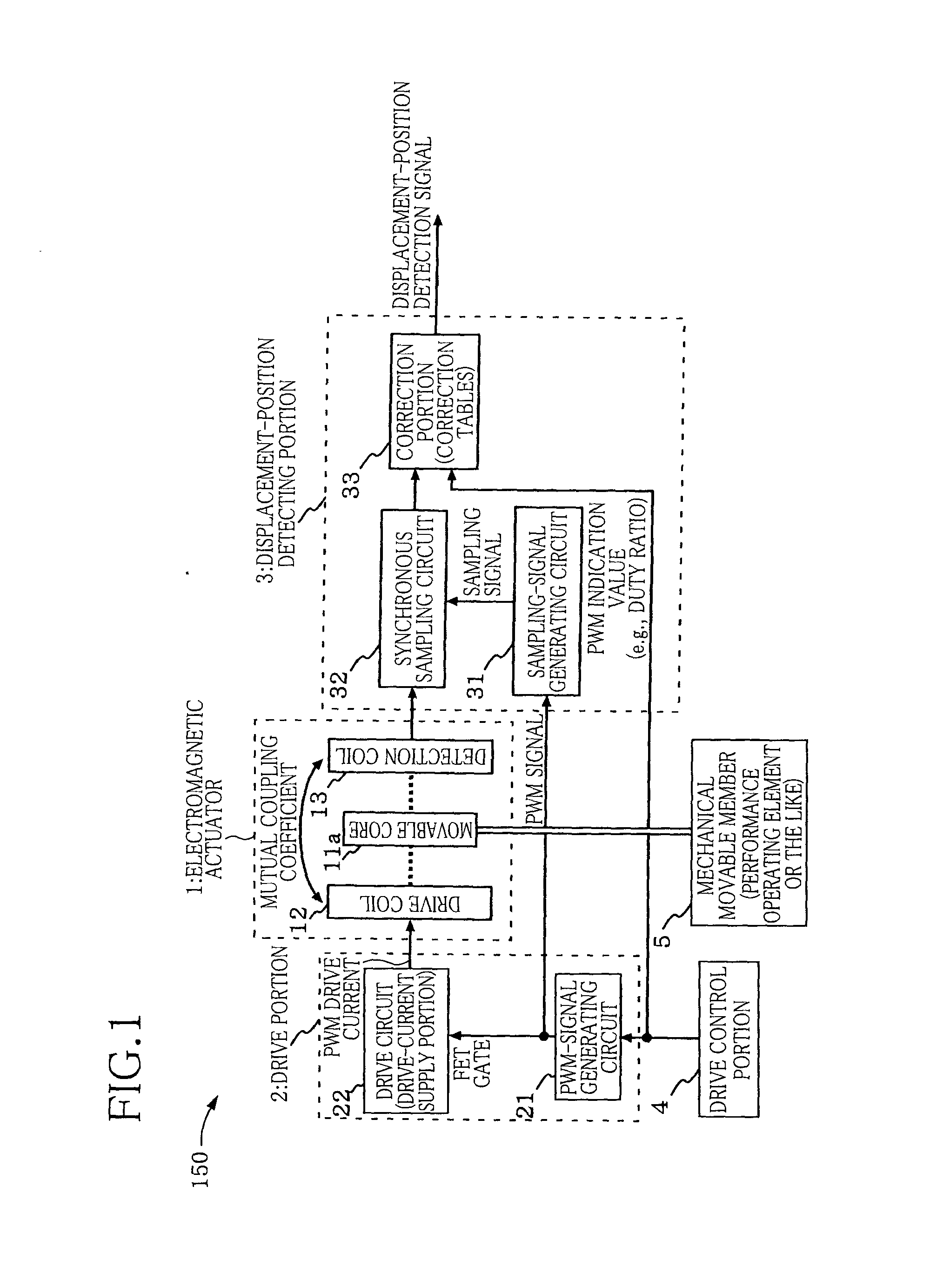
[0035]FIG. 1 is a functional block diagram for explaining a detecting apparatus for detecting a displacement of an electromagnetic actuator according to one embodiment of the present invention. The detecting apparatus generally indicated at 150 in FIG. 1 is constituted by an electromagnetic actuator 1, a drive portion 2, and a displacement-position detecting portion 3. The electromagnetic actuator 1 shown in FIG. 1 includes a movable core (movable iron core) 11a and a drive coil 12. The movable core 11a is formed of a magnetic material and is one constituent element of a plunger 11 shown in FIG. 2. The electromagnetic actuator 1 transmits a drive force generated by electromagnetic induction to a mechanical movable member 5 such as a performance operating element like a key or a pedal of an electronic keyboard musical instrument, or a valve of an internal combustion engine. The electromagnetic actuator 1 additionally includes a detection coil 13.

[0036]The drive portion 2 is configure...


PUM


Abstract

A displacement detecting apparatus of an electromagnetic actuator, including: an electromagnetic actuator including: a movable core; a drive coil which causes a displacement of the movable core; and a detection coil disposed at a position where a mutual coupling coefficient with the drive coil changes with the displacement, the actuator transmitting a drive force of the movable core to a mechanical system; a drive portion for supplying a drive current to the drive coil on the basis of a pulse width modulation signal; and a displacement detecting portion to which an output voltage of the detection coil is inputted, for outputting a displacement detection signal, wherein the displacement detecting portion includes: a sampling-signal generating portion for generating a sampling signal in synchronism with the pulse width modulation signal; and a synchronous sampling portion for outputting the displacement detection signal by sampling the output voltage in synchronism with the sampling signal.

Description

CROSS REFERENCE TO RELATED APPLICATION[0001]The present application claims priority from Japanese Patent Application No. 2010-069938, which was filed on Mar. 25, 2010, the disclosure of which is herein incorporated by reference in its entirety.BACKGROUND OF THE INVENTION[0002]1. Field of the Invention[0003]The present invention relates to an apparatus for detecting a displacement of an electromagnetic actuator driven by a pulse width modulation signal. The electromagnetic actuator is used for generating a reaction force with respect to manipulation by a user and for allowing operating elements or members, valves and the like to be automatically operated, for instance.[0004]2. Discussion of Related Art[0005]In a keyboard apparatus of an electronic keyboard musical instrument, a drive mechanism is provided for each key to execute a control for increasing and decreasing a key touch feeling felt by a performer or player in a performance operation, i.e., a force sense control, or for all...

Claims


Application Information

Patent Timeline
IPC IPC(8): G01B7/14
CPCG01B7/003G01D5/2046H01F7/1607H01F7/1653H01F2007/1888H01F2007/1684H01F2007/1692H01F2007/185H01F7/1844
Inventor HAYASHI, YOSHINORIKOMATSU, AKIHIKO
Owner YAMAHA CORP
Why Eureka
Try Eureka