High-frequency switch module

a high-frequency switch and module technology, applied in the field of high-frequency switch modules, can solve the problems of increased discharge time and difficulty in releasing an electric charge stored in the switch ic, and achieve the effect of quick discharge of an electric charge stored, high-speed switching

Active Publication Date: 2011-09-29
MURATA MFG CO LTD
View PDF7 Cites 19 Cited by
  • Summary
  • Abstract
  • Description
  • Claims
  • Application Information

AI Technical Summary

Benefits of technology

[0010]Preferred embodiments of the present invention provide a high-frequency switch module that quickly discharges an electric charge stored in a switch IC and achieves high-speed switching.

Problems solved by technology

However, since the capacitor is directly connected to the antenna connection port in the above-described high-frequency switch modules in the related art, it is difficult for an electric charge stored in the switch IC to discharge and a discharge time is increased.

Method used


Image

  • High-frequency switch module
  • High-frequency switch module
  • High-frequency switch module

Examples


Embodiment Construction

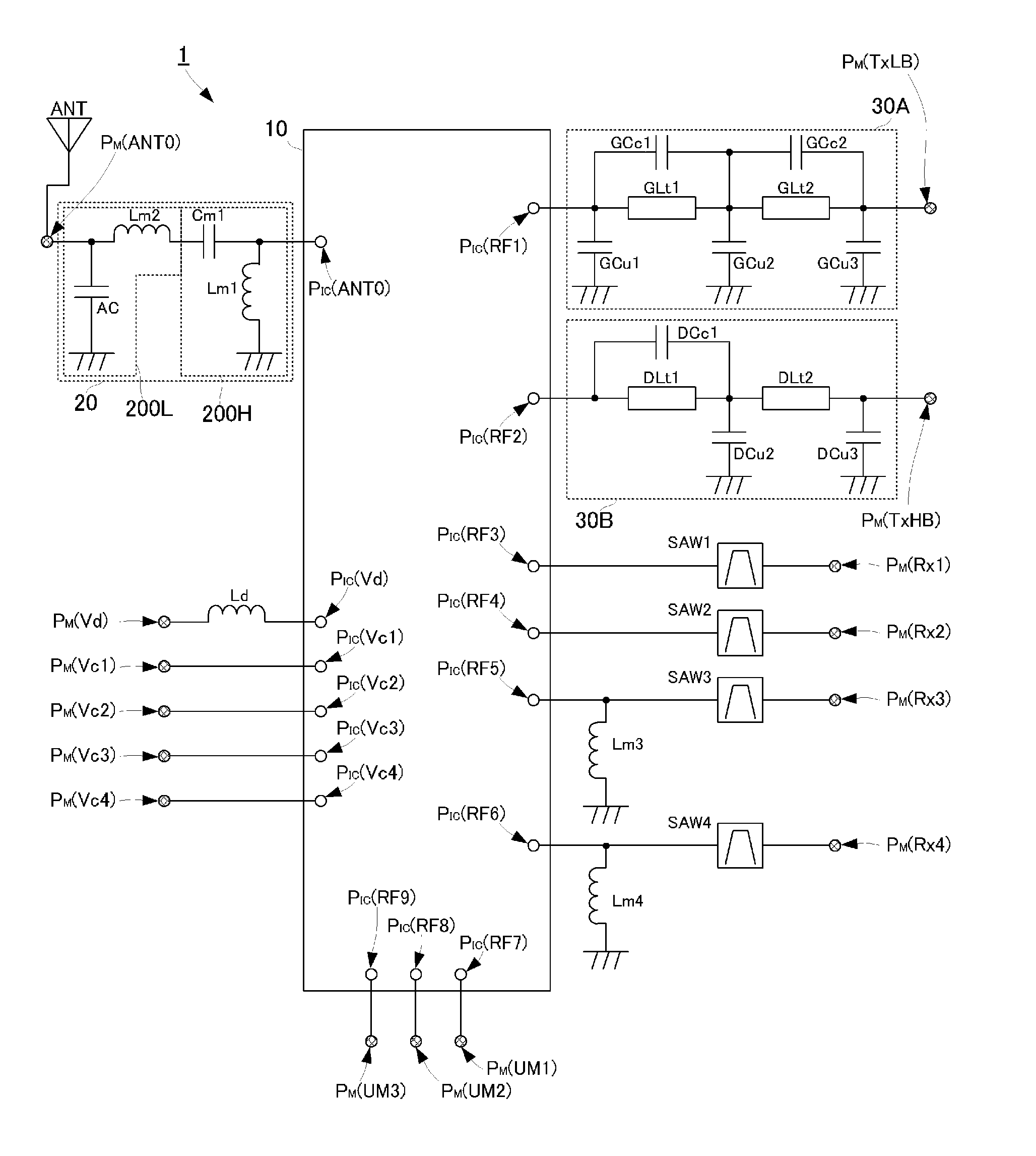
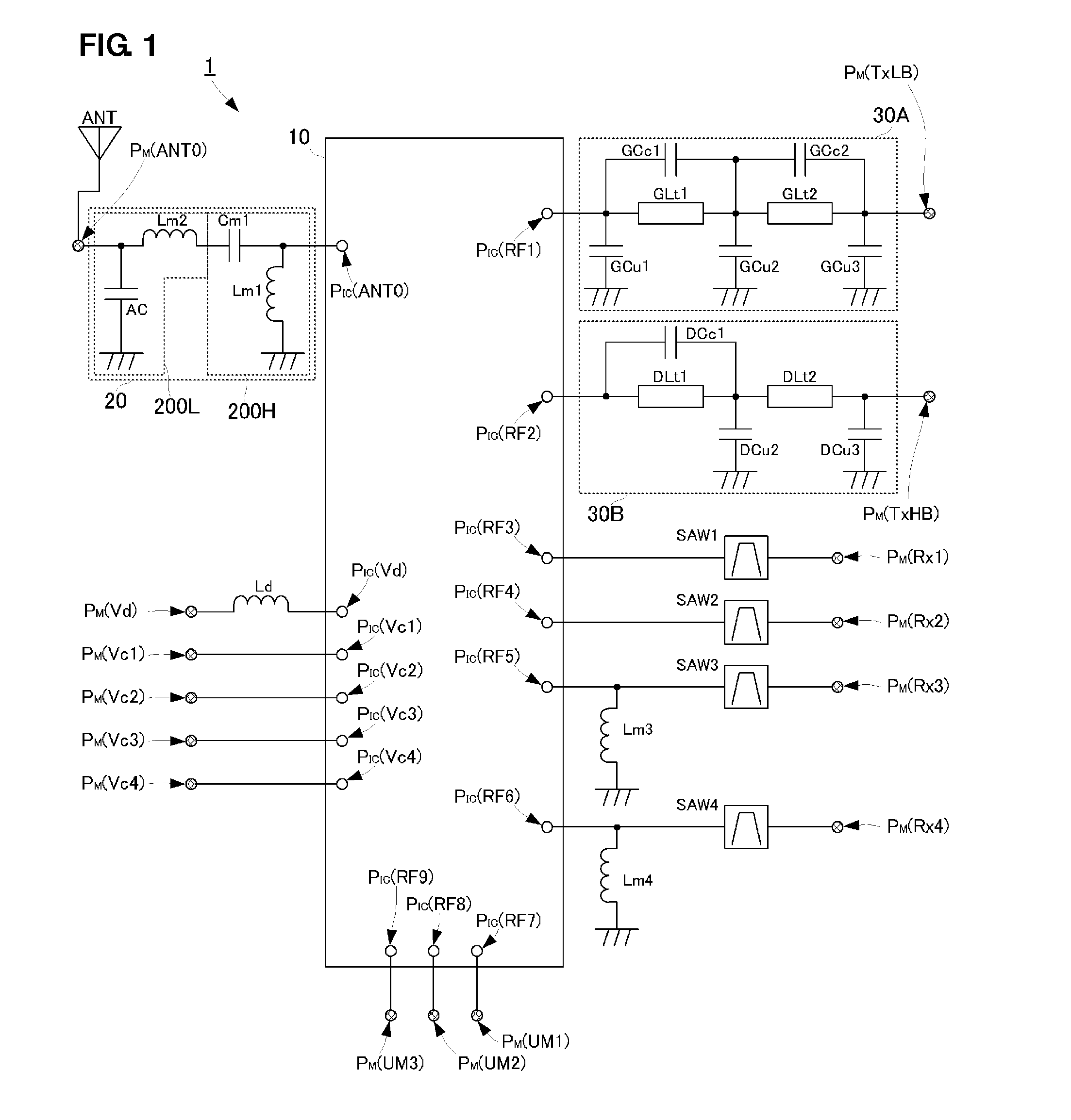
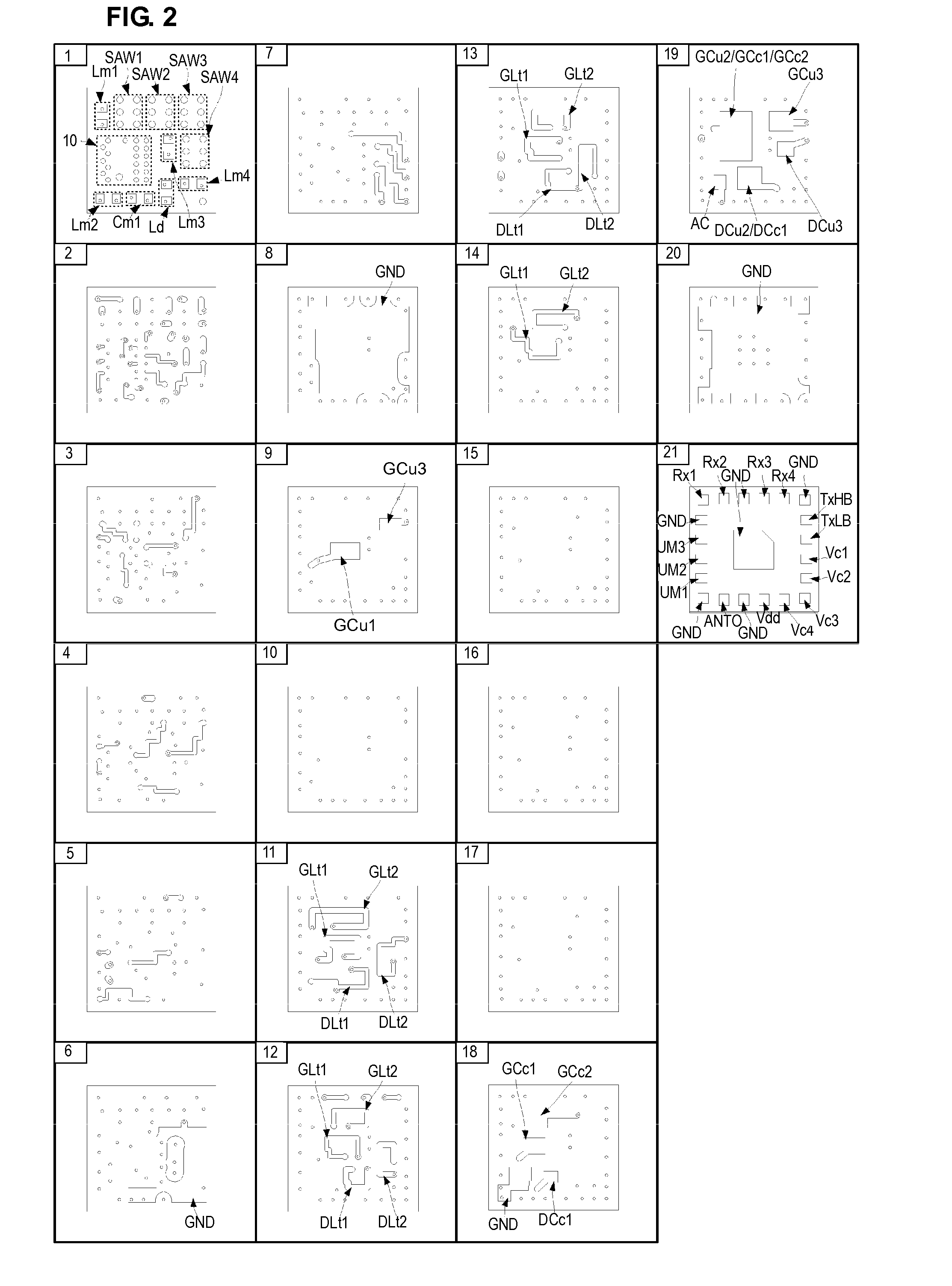
[0038]A high-frequency switch module according to a first preferred embodiment of the present invention will be described with reference to the accompanying drawings. FIG. 1 is a circuit diagram of a high-frequency switch module 1 according to the first preferred embodiment. FIG. 2 is a lamination diagram of a multilayer circuit board in the high-frequency switch module 1.

[0039]A multilayer circuit board in the high-frequency switch module 1, whose configuration will be described in detail later with reference to FIG. 2, includes a stack of a plurality of dielectric layers made of ceramic or a resin. Circuit patterns other than a switch IC 10, inductors Lm1, Lm2, Lm3, Lm4, and Ld, a capacitor Cm1, and SAW filters SAW1, SAW2, SAW3, and SAW4 in the switch IC 10 illustrated in FIG. 1 are created by forming electrodes of predetermined patterns in inner layers between the dielectric layers and the top and bottom surfaces of the stack.

[0040]The high-frequency switch module 1 includes a pl...


PUM


Abstract

A high-frequency switch module includes a switch IC. An impedance matching circuit is connected to the antenna port of the switch IC. The impedance matching circuit includes a high-pass filter and a low-pass filter. The high-pass filter is disposed on the side of the antenna port, and is a substantially L-shaped circuit including a capacitor and an inductor. The antenna port is connected to the ground by the inductor.

Description

BACKGROUND OF THE INVENTION[0001]1. Field of the Invention[0002]The present invention relates to a high-frequency switch module arranged to switch among various high-frequency signals to be transmitted or received.[0003]2. Description of the Related Art[0004]Various high-frequency switch modules for transmitting / receiving a plurality of communication signals in different frequency bands with a single antenna have been recently developed. In such a high-frequency switch module, an SPnT (n represents a positive number) switch IC is generally used. The SPnT switch IC includes an antenna connection port connected to an antenna and a plurality of high-frequency signal input / output ports (including a transmission port, a reception port, and a transmission / reception port.) Switching among the high-frequency signal input / output ports to be connected to the antenna connection port is performed in accordance with a control signal.[0005]In high-frequency switch modules in the related art, a ma...

Claims


Application Information

Patent Timeline
Patent Type & Authority Applications(United States)
IPC IPC(8): H03K17/00
CPCH03H7/0123H03H7/1766H03H7/38H04B1/18H03H2001/0085H04B1/0458H03H7/465
Inventor UEJIMA, TAKANORIMURASE, HISANORI
Owner MURATA MFG CO LTD
Why Eureka
Try Eureka