Decoding apparatus, decoding method, program and integrated circuit

Inactive Publication Date: 2011-09-29
PANASONIC CORP
View PDF16 Cites 11 Cited by
  • Summary
  • Abstract
  • Description
  • Claims
  • Application Information

AI Technical Summary

Benefits of technology

[0035]The present invention provides an advantageous effect of making it possible to implement a decoding apparatus capable of r

Problems solved by technology

However, depending on an image, a motion vector that is generated in the direct mode may not be the optimum motion vector.
A non-optimum motion vector decreases the amount of motion vector information but increases the amount of coefficient information correspo

Method used


Image

  • Decoding apparatus, decoding method, program and integrated circuit
  • Decoding apparatus, decoding method, program and integrated circuit
  • Decoding apparatus, decoding method, program and integrated circuit

Examples


embodiment 1

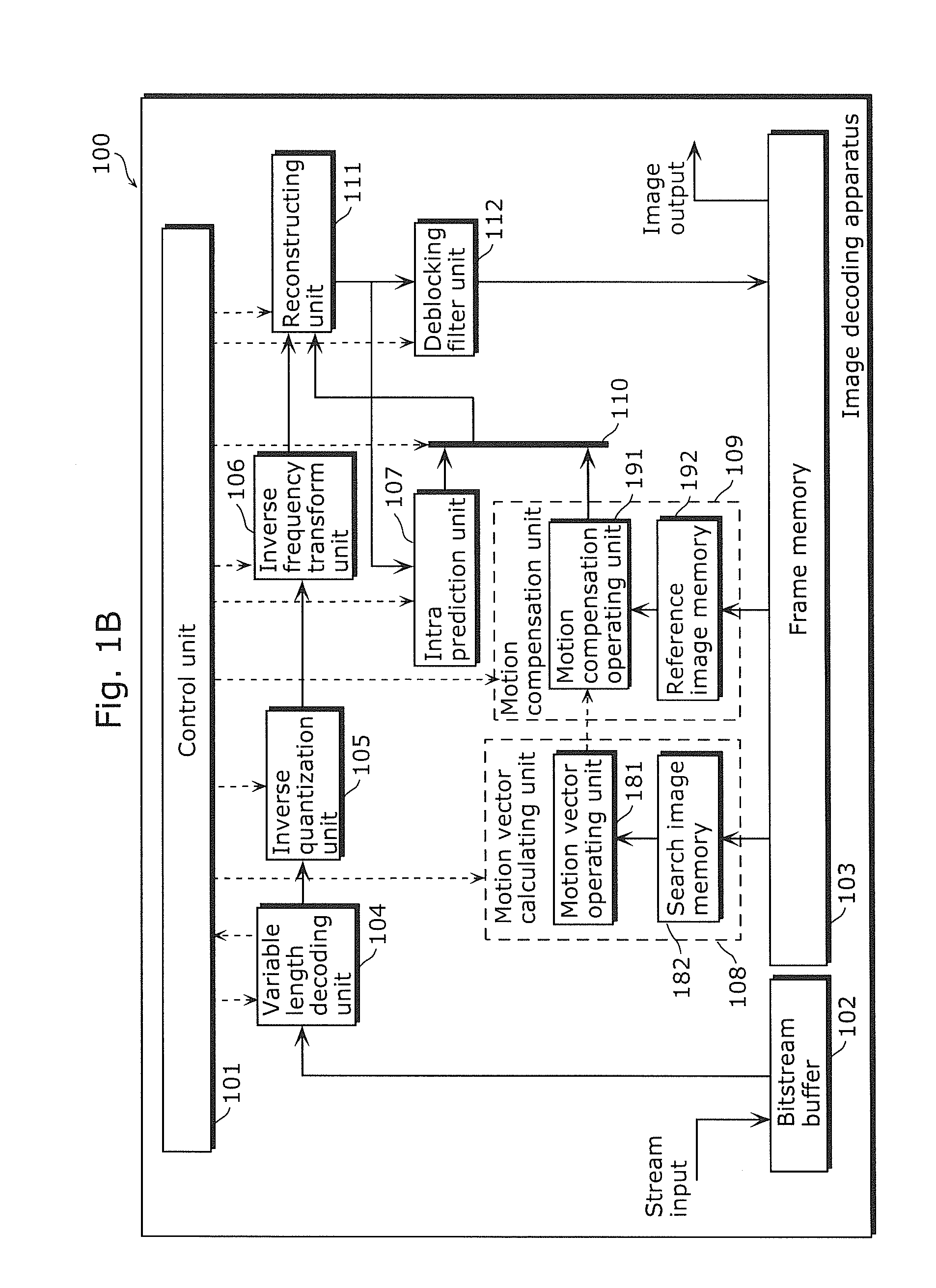
[0078]An image decoding apparatus according to Embodiment 1 of the present invention is schematically described. The image decoding apparatus according to Embodiment 1 of the present invention performs variable length decoding on a coded stream (coded image) in units of a macroblock that constitute a part of the coded image. Next, in the case where a current macroblock is a direct mode, the image decoding apparatus reads out the pixel data in a search area (also referred to as “search image”) in a reference image, and stores the pixel data of a search image memory. The image decoding apparatus is configured to determine a motion vector by repeatedly reading out, for each macroblock, the pixel data in the search area from the search image memory and performing a predetermined operation on the pixel data.

[0079]This is the outline of the image decoding apparatus according to the present invention.

[0080]Next, the structure of the image decoding apparatus 100 in Embodiment 1 is described...

embodiment 2

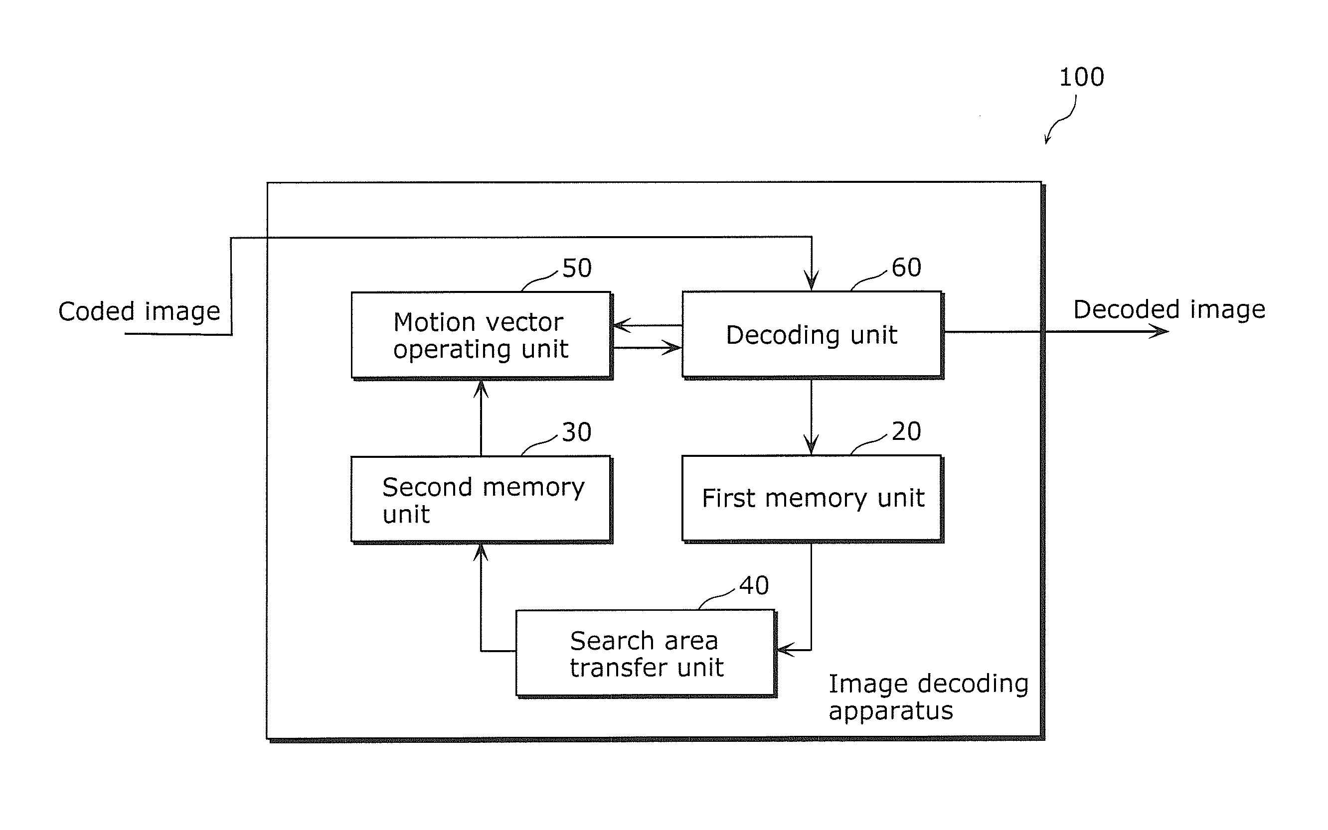
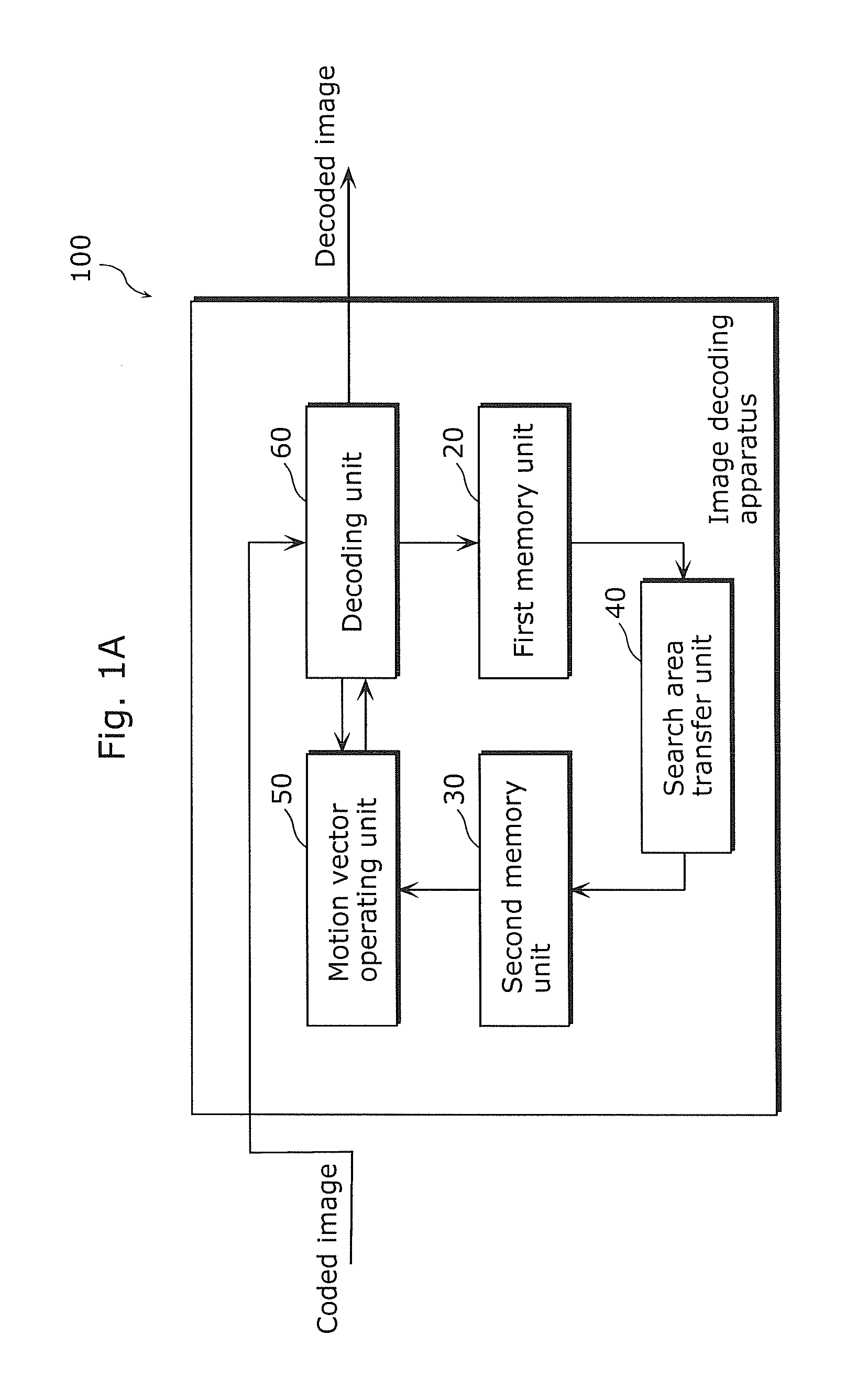
[0112]Next, an image decoding apparatus according to Embodiment of the present invention is schematically described. In Embodiment 1, a search image is transferred after inverse frequency transform, only in the case of a direct mode. For this reason, a useless waiting time is produced because a motion vector search process must be performed after the transfer of the search image is completed. In view of this, in Embodiment 2, a motion vector calculating unit further includes a search image transfer unit (search area transfer unit). With this, it is possible to eliminate such a waiting time by starting the transfer of a search image before starting a motion vector calculation process. As a result, it is possible to increase the processing performance and reduce the band width required for transfer from a frame memory.

[0113]The outline of the image decoding apparatus in Embodiment 2 has been described above.

[0114]Next, the structure of the image decoding apparatus 200 in Embodiment 2 ...

embodiment 3

[0139]Next, an image decoding apparatus according to Embodiment 3 of the present invention is schematically described. In Embodiments 1 and 2, search image transfer is performed for each macroblock to be decoded. The search area necessary to calculate a motion vector for a first macroblock is shifted to the right by only 16 pixels to determine the search area necessary for a second macroblock next to the first macroblock. Thus, most of the pixels can be re-used for the next search. Accordingly, only the pixels necessary for the next search is transferred from a frame memory to a search image memory.

[0140]In this way, it is possible to reduce the transfer amount and the band width required for the transfer. The outline of the image decoding apparatus in Embodiment 3 has been described above.

[0141]Next, the structure of the image decoding apparatus 200 in Embodiment 3 is described. The structure of the image decoding apparatus 200 in Embodiment 3 is the same as in FIG. 4 in Embodiment...


PUM


Abstract

A decoding apparatus (100) includes: a first memory unit (20) storing pixel data of a decoded reference image to be referred to in decoding; a second memory unit (30) having a storage capacity smaller than that of the first memory unit (20) and providing a data reading speed faster than that provided by the first memory unit (20); a search area transfer unit (40) transferring, from the first memory unit (20) to the second memory unit (30), pixel data in a search area that is a part of the reference image and required to calculate a motion vector for the block; a motion vector operating unit (50) calculating the motion vector by repeatedly (i) reading out, from the second memory unit (30), the pixel data and (ii) performing a predetermined operation on the pixel data; and a decoding unit (60) decoding the block using the calculated motion vector.

Description

TECHNICAL FIELD[0001]The present invention relates to image decoding apparatuses which decode coded images and image decoding methods, and in particular to image decoding apparatuses which perform correlation search of decoded images with respect to images to be decoded and image decoding methods performed thereby.BACKGROUND ART[0002]An image coding apparatus which codes a moving picture divides each of the pictures making up the moving picture into macroblocks each composed of 16×16 pixels, and codes each picture in units of a macroblock. The image coding apparatus generates a coded stream obtained by compressing and coding the moving picture. An image decoding apparatus decodes this coded stream in units of a macroblock, and reproduces each of the pictures in the original moving picture.[0003]Conventional image coding standards include the ITU-T H.264 Standard (for example, see NPL (Non-patent Literature) 1 and NPL 2. As shown in FIG. 30, an image decoding apparatus conforming to ...

Claims


Application Information

Patent Timeline
IPC IPC(8): H04N7/26
CPCH04N19/433H04N19/44
Inventor TANAKA, TAKESHIAMANO, HIROSHIHAYASHI, YOSHITERUHASHIMOTO, TAKASHIKAJITA, SATOSHI
Owner PANASONIC CORP
Why Eureka
Try Eureka