Method and base station for receiving reference signal, and method and user equipment for receiving reference signal

a reference signal and base station technology, applied in the field of reference signal transmission methods and methods and apparatuses for receiving reference signals, can solve problems such as unexpected distortion of transmission signals

Active Publication Date: 2011-09-29
LG ELECTRONICS INC
View PDF5 Cites 222 Cited by
  • Summary
  • Abstract
  • Description
  • Claims
  • Application Information

AI Technical Summary

Benefits of technology

[0177]According to the above-described embodiments of the present invention, RSs for channel measurement can be transmitted to a UE while minimally affecting other physical signals.
[0178]According to the present invention, transmission efficiency of RSs for channel measurement can be raised.
[0011]The present invention provides a method and apparatus for receiving a reference signal for channel measurement and perform channel measurement by using the reference signal.
[0180]According to the present invention, a UE can efficiently feed back channel information to a BS.

Problems solved by technology

During signal transmission, unexpected distortion may occur in the transmission signals.

Method used


Image

  • Method and base station for receiving reference signal, and method and user equipment for receiving reference signal
  • Method and base station for receiving reference signal, and method and user equipment for receiving reference signal
  • Method and base station for receiving reference signal, and method and user equipment for receiving reference signal

Examples


embodiment 1

1. Embodiment 1

Non-Transmission of CSI-RS in PSS / SSS / PBCH Subframe

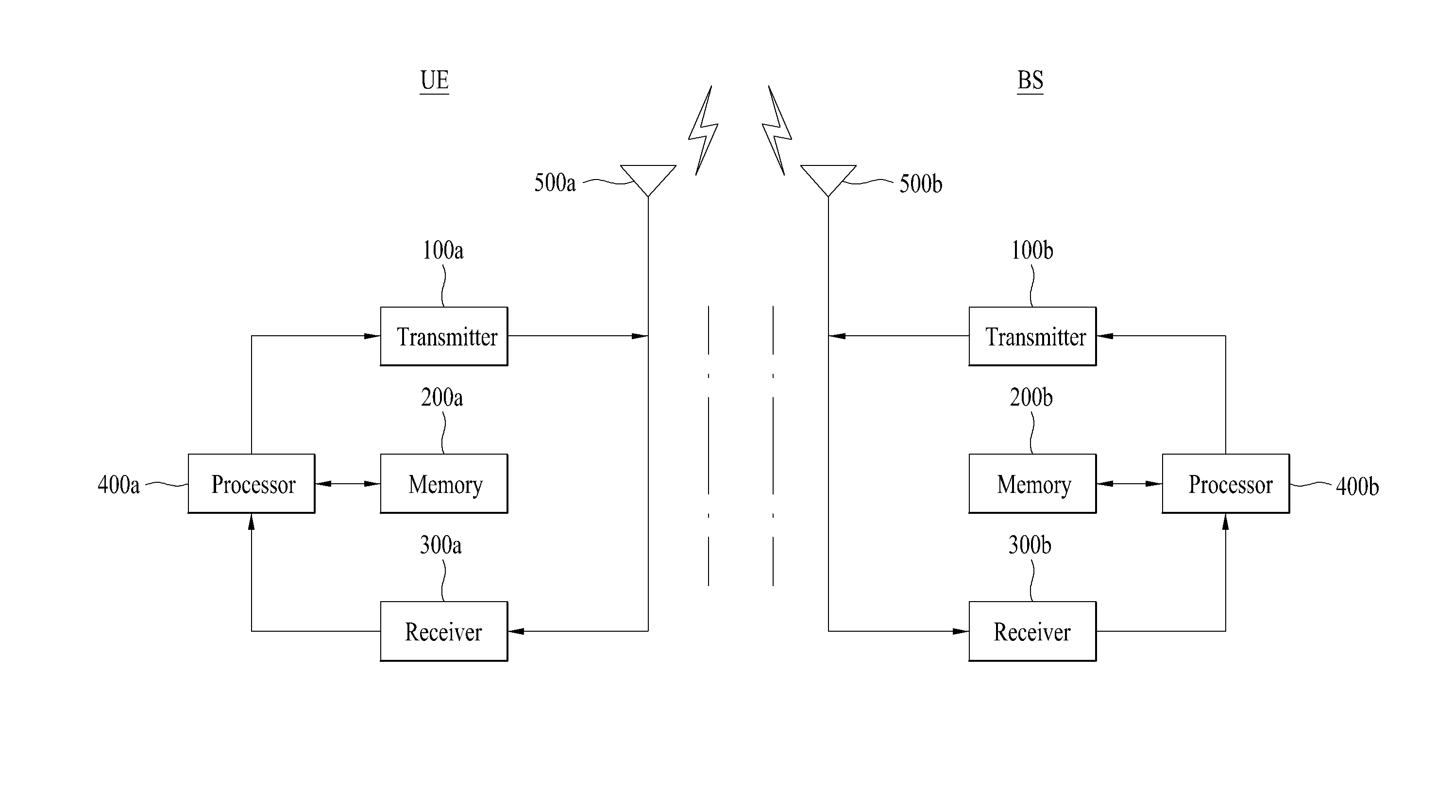
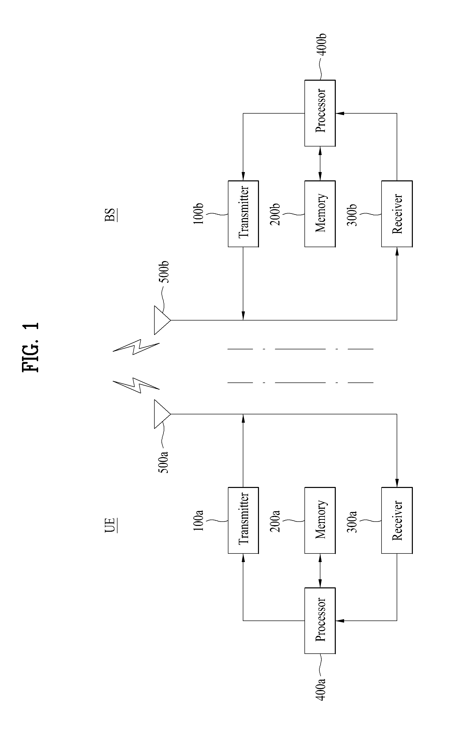
[0126]If a subframe for PSS, SSS, or PBCH transmission collides with a subframe for CRS-RS transmission, a BS may not transmit CSI-RSs in the colliding subframe. If CSI-RS transmission in a subframe configured for CSI-RS transmission collides with synchronization signal or broadcast signal transmission, the BS processor 400b configured according to Embodiment 1 of the present invention may not control the BS transmitter 100b to transmit CSI-RSs in that subframe. Namely, according to Embodiment 1, no CSI-RSs are transmitted in a subframe in which PSS / SSS / PBCH are transmitted (i.e., in a colliding CSI-RS subframe) among CSI-RS subframes. However, if a subframe configured for CSI-RS transmission differs from a subframe in which the PSS / SSS / PBCH are transmitted, the BS processor 400b controls the BS transmitter 100b to perform CSI-RS transmission in the CSI-RS subframe as long as there is no other reason. Namely, as long ...

embodiment 2

2. Embodiment 2

Non-Transmission of CSI-RSs in RBs Including PSS / SSS / PBCH

[0132]When a subframe for PSS, SSS, or PBCH transmission collides with a subframe for CSI-RS transmission, a BS may not transmit CSI-RSs in RBs carrying PSS / SSS / PBCH among RBs in the colliding subframe. The BS may not transmit any CSI-RS in 6 RBs adjacent to a DC subcarrier in the colliding subframe. The BS processor 400b configured according to Embodiment 2 may control the BS transmitter 100b, when a CSI-RS subframe is identical to a PSS / SSS / PBCH subframe, to perform CSI-RS transmission in an RB not carrying PSS / SSS / PBCH in a CSI-RS subframe and not to perform CSI-RS transmission in an RB not carrying PSS / SSS / PBCH in the CSI-RS subframe.

[0133]The BS may transmit data signals instead of CSI-RSs on REs except for PSS / SSS / PBCH REs among CSI-RS REs in 6 RBs including the PSS / SSS / PBCH in a colliding subframe. If a CSI-RS RE configured for CSI-RS transmission is present in an RB including PSS / SSS / PBCH, the BS process...

embodiment 3

3. Embodiment 3

Non-Transmission of CSI-RSs in Subframes Including CSI-RS REs Colliding with PSS / SSS / PBCH REs

[0138]According to Embodiment 1 and Embodiment 2, no CSI-RS is transmitted over an entire frequency band of a CSI-RS subframe colliding with a PSS / SSS / PBCH subframe or a frequency band corresponding to 6 RBs carrying PSS / SSS / PBCH in the CSI-RS subframe, irrespective of a CSI-RS pattern. However, even if a CSI-RS subframe collides with a PSS / SSS / PBCH subframe, CSI-RS REs may not collide with PSS / SSS / PBCH REs.

[0139]FIG. 17 illustrates exemplary RB pairs in which CSI-RSs are transmitted and exemplary RB pairs in which PSS / SSS / PBCH are transmitted. In particular, FIG. 17(a) illustrates RB pairs including PSS / SSS / PBCH in a frame structure with a normal CP in FDD mode, and FIG. 17(b) illustrates RB pairs including the CSI-RS pattern of FIG. 15(b). It is assumed in FIG. 17 that CSI-RSs are transmitted in a form shown in FIG. 13.

[0140]Referring to FIG. 17, a BS operating in FDD mode t...


PUM


Abstract

A base station does not transmit any reference signal (RS) for channel measurement in a subframe in which transmission of an RS collides with transmission of a synchronization signal or a broadcast signal or in a resource block including the synchronization signal or the broadcast signal in the subframe. A user equipment assumes that any RS for channel measurement is not transmitted in a subframe or in a resource block when transmission of an RS collides with transmission of a synchronization signal or a broadcast signal in the subframe or in the resource block.

Description

CROSS-REFERENCE TO RELATED APPLICATIONS[0001]This application claims the benefit of U.S. Provisional Application Ser. Nos. 61 / 317,709, filed on Mar. 26, 2010, and 61 / 392,480, filed on Oct. 13, 2010, which are hereby incorporated by references as if fully set forth herein.[0002]This application also claims the benefit of Korean Patent Application No. 10-2011-0026299, filed on Mar. 24, 2011, which is hereby incorporated by reference as if fully set forth herein.BACKGROUND OF THE INVENTION[0003]1. Field of the Invention[0004]The present invention relates to a wireless communication system, and more particularly, to a method and apparatus for transmitting a reference signal, and method and apparatus for receiving the reference signal.[0005]2. Discussion of the Related Art[0006]A transmitter in a wireless communication system transmits signals through radio frequency channels. During signal transmission, unexpected distortion may occur in the transmission signals. Also, the transmitter m...

Claims


Application Information

Patent Timeline
Patent Type & Authority Applications(United States)
IPC IPC(8): H04L27/00
CPCH04L5/0048H04L5/0023H04L5/0053H04L5/0082H04L5/0091H04L5/0073H04L27/261H04W72/23H04J11/00H04J2011/0096H04L5/0007
Inventor LEE, MOON ILCHUNG, JAE HOONKO, HYUN SOOHAN, SEUNG HEE
Owner LG ELECTRONICS INC
Why Eureka
Try Eureka