Method and System for Super-Resolution Blind Channel Modeling

a blind channel and super-resolution technology, applied in the field of channel measurement, channel estimation and channel modeling of wireless channels, can solve the problems of poor performance and inability of modeling techniques to model parts of the band, and achieve the effect of significant performance gain

Inactive Publication Date: 2011-09-29
MITSUBISHI ELECTRIC RES LAB INC
View PDF6 Cites 6 Cited by
  • Summary
  • Abstract
  • Description
  • Claims
  • Application Information

AI Technical Summary

Benefits of technology

[0012]Finally, estimates derived from different subbands are combined via a soft combining technique. The super-resolution blind method can achieve a significant performance gain over conventional methods.

Problems solved by technology

Conventional channel modeling techniques cannot model parts of the band where no sounding signals are available; or, if the techniques use conventional interpolation, suffer from poor performance.

Method used


Image

  • Method and System for Super-Resolution Blind Channel Modeling
  • Method and System for Super-Resolution Blind Channel Modeling
  • Method and System for Super-Resolution Blind Channel Modeling

Examples


Embodiment Construction

[0019]The embodiments of our invention provide a method for estimating a frequency response of a wideband channel, and subsequently extracting a channel model when only measurements in parts of the wideband channel are available, specifically in disjoint frequency subbands.

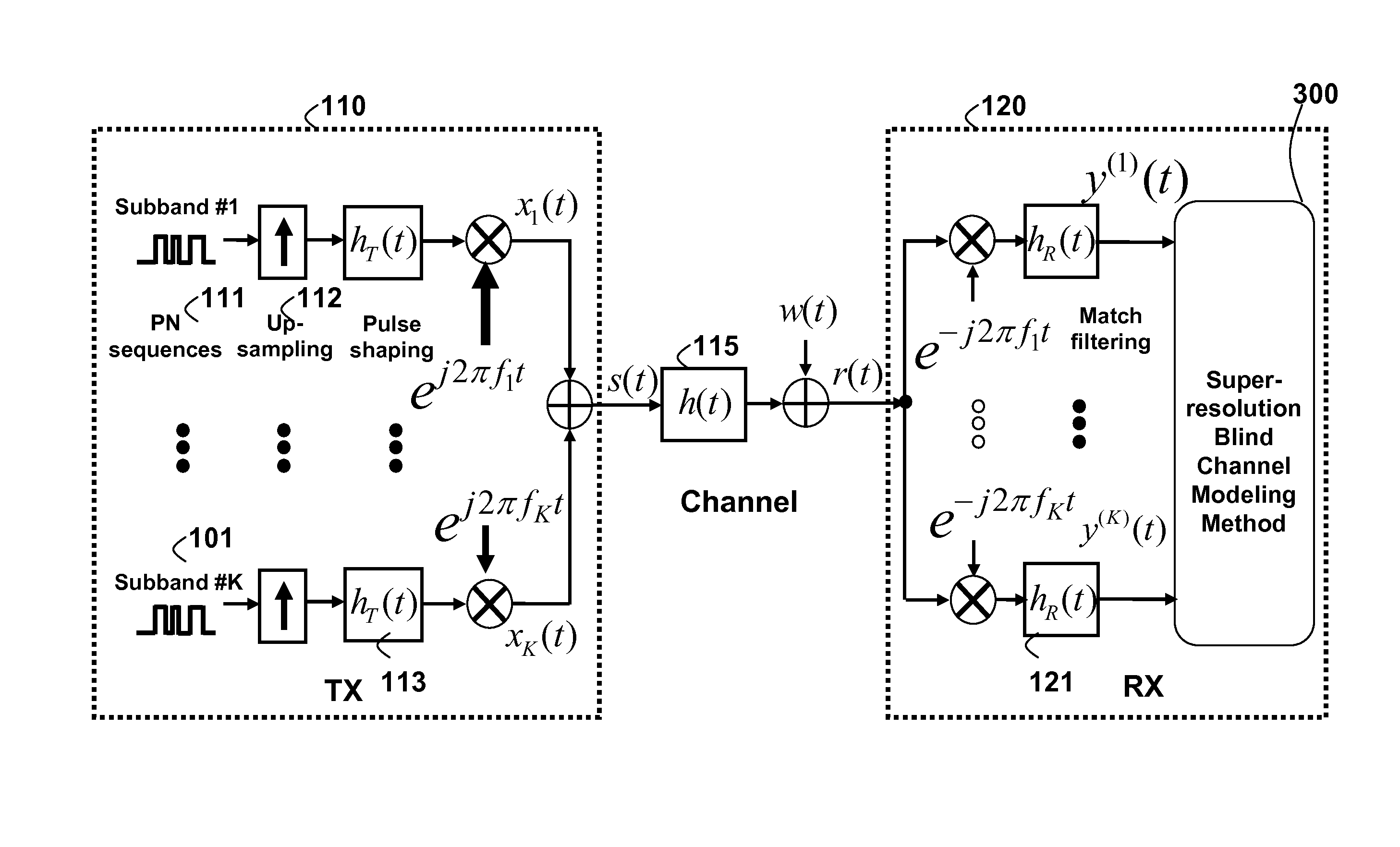
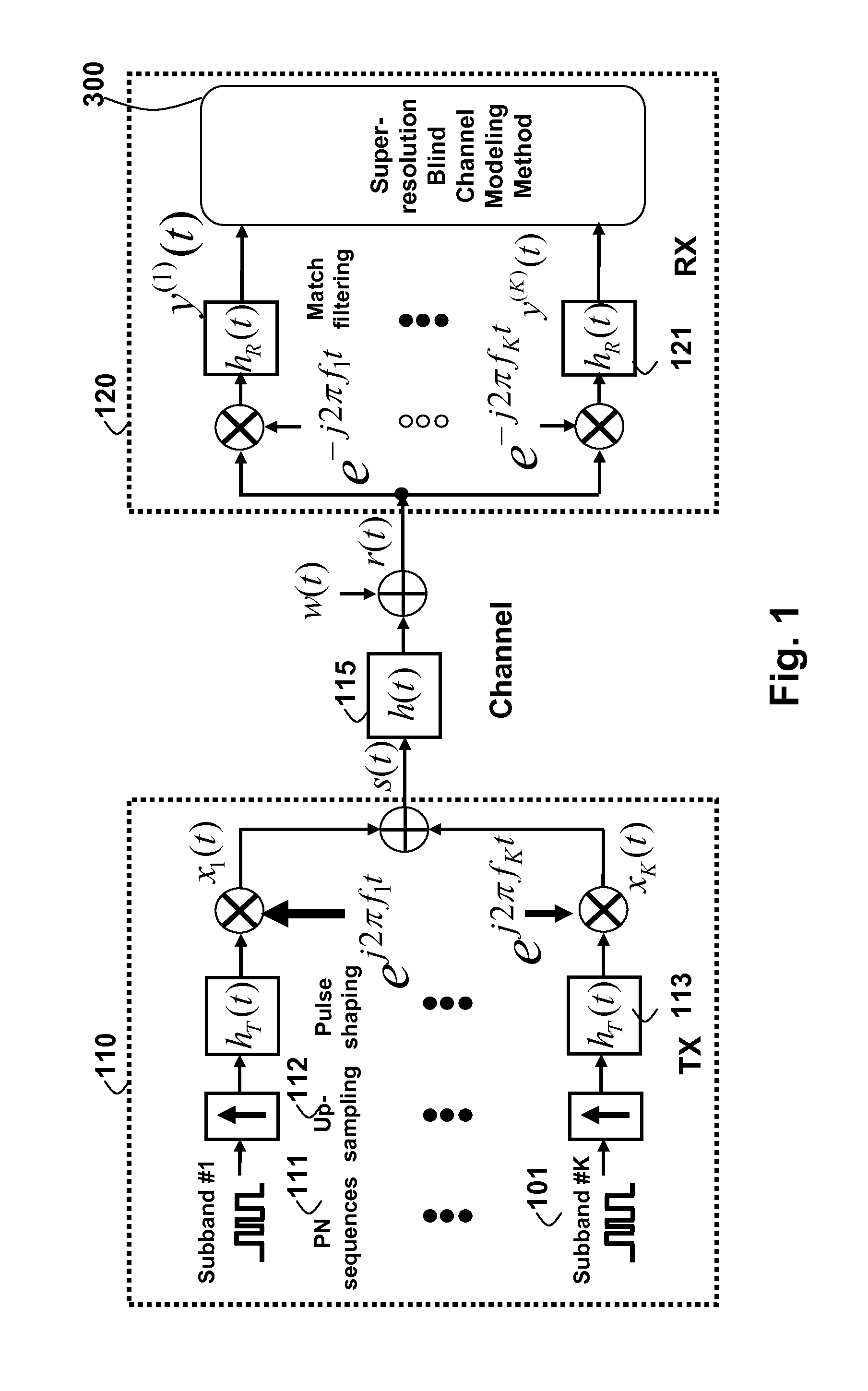
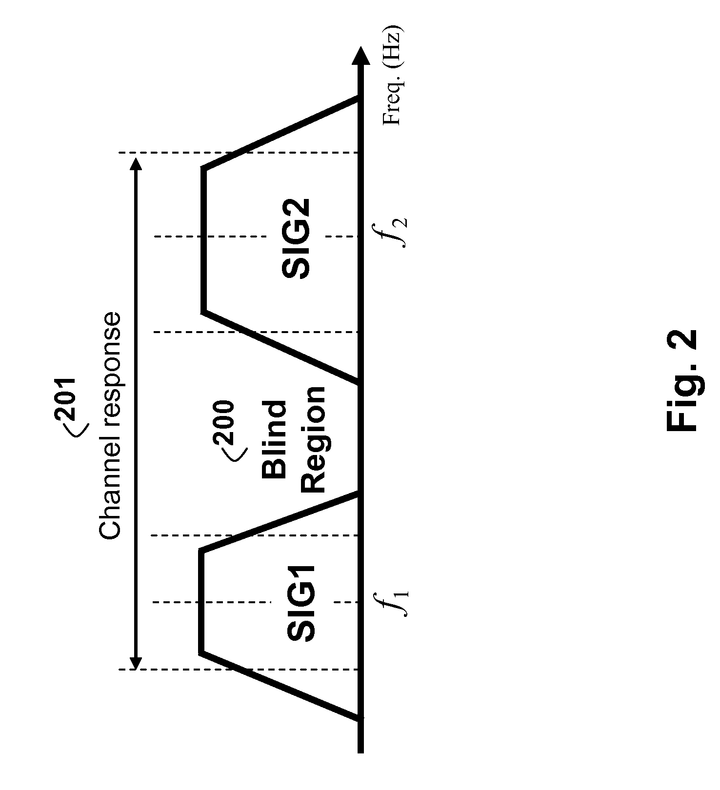
[0020]As show in FIG. 1, the system includes a transmitter TX) 110 and a receiver (RX) 120 connected by a wireless channel 115. The system uses of K disjoint narrowband subbands 101 separated by guard bands (also referred to as the blind regions). FIG. 2 illustrates a particular case with K=2 subbands. Note that the bandwidth of each subband, or guard band can differ.

[0021]As shown in FIG. 1, a sounding signal comprising of G repeated pseudo-noise (PN) sequences 111 is first up-sampled 112 before being fed into a pulse shaping filter hT(t) 113, such as a square-root raised cosine filter. After that, the pulsed-shaped signal is up-converted to fk and transmitted through the kth subband. As a result, the transmit si...


PUM


Abstract

Propagation channels are reconstructed from measurements in disjoint subbands of a wideband channel of interest. By using high-resolution estimation of multipath parameters, and suitable soft combining of the results, a channel estimate and subseqeuntly channel models can be extracted that accurately interpolate between the measured subbands.

Description

FIELD OF THE INVENTION[0001]This invention relates generally to channel measurement, channel estimation and channel modeling for wireless channels.BACKGROUND OF THE INVENTION[0002]Accurate characterization of wireless propagation channels plays a critical role in designing high-performance wireless systems. As demonstrated in Shannon's seminal work, the fundamental performance limits of wireless transmission are dictated by the wireless channel characteristics. Hence, an in-depth understanding of the underlying channel can facilitate system architects to design, optimize and subsequently analyze practical wireless systems.[0003]For the purpose of system development, channel models based on measurements are essential. Conventionally, channel measurements are performed by sending and measuring sounding signals over the entire frequency band of interest. However, there are often challenging situations in which sounding signals can be transmitted only over some parts of the frequency ba...

Claims


Application Information

Patent Timeline
Patent Type & Authority Applications(United States)
IPC IPC(8): H04B17/00
CPCH04L25/0206H04L25/0212H04B17/3911H04L25/0226H04L25/0238H04L25/022H04L25/0204
Inventor PUN, MAN-ONORLIK, PHILIP V.
Owner MITSUBISHI ELECTRIC RES LAB INC
Why Eureka
Try Eureka