Method for fibrous anchoring of a pelvic support

a pelvic support and fibrous technology, applied in the field of pelvic support fibrous anchoring, can solve the problems of high vascular injury rate, disadvantageous requirement for needles to exit the lower abdominal wall, and comparatively large needles used for inserting tapes, so as to minimize the medial presentation of the retaining means and hinder the movement of the implan

Inactive Publication Date: 2011-09-29
COLOPLAST AS
View PDF99 Cites 46 Cited by
  • Summary
  • Abstract
  • Description
  • Claims
  • Application Information

AI Technical Summary

Benefits of technology

[0024]It is preferable if at least one of the retaining means of the implant is moveable from a collapsed position to an extended position as it enables the retaining means to actively move into tissue in at least one layer of the tissue following suitable location of the implant. The movement of the retaining means from a collapsed position to an extended position allows the means to move into and be retained in tissue which has been undisturbed or which has not been disrupted during placement of the implant. The collapsed position of the implant can be achieved by rolling up, folding, bending, or enclosing the implant in a restrained position.
[0441]It is possible to determine whether or not the bladder of a patient has been perforated by a surgical implant or instrument when inserting the surgical implant of the invention into the body, by expelling a small amount of fluid from the bladder, and determining whether or not this small amount of fluid contains any dissolved dye.

Problems solved by technology

Whilst highly effective in treating urinary incontinence, this procedure has a number of problems.
One such problem is that the needles used for inserting the tape are comparatively large, with the needles having, for example, a diameter of around 5-6 mm and a length of around 200 mm.
As well as causing concern for patients viewing such needles before or during the procedure (which is carried out under local anesthetic), this can also lead to a high vascular injury rate.
Similarly, the requirement that the needles exit the lower abdominal wall is disadvantageous due to the trauma to the patient in this area and pain of such abdominal wounds.
A further disadvantage is that the tape comprises a relatively large foreign body mass to be retained within the patient and this can lead to related inflammation, infection translocation, erosion, fistula and such like.
Similarly, the nature of the large needles and tape, along with the tools required to insert these in the body, lead to the procedure having a relatively high cost.
The requirement that the needles exit the body over the obturator foramen is disadvantageous due to the trauma to the patient in this area and pain of such wounds.
A further disadvantage is that the implant comprises a relatively large foreign body mass to be retained within the patient and this can lead to related inflammation, infection translocation, erosion, fistula and such like.
Furthermore, anatomical damage to nerves and blood vessels may occur during procedures which penetrate the obturator foramen.

Method used


Image

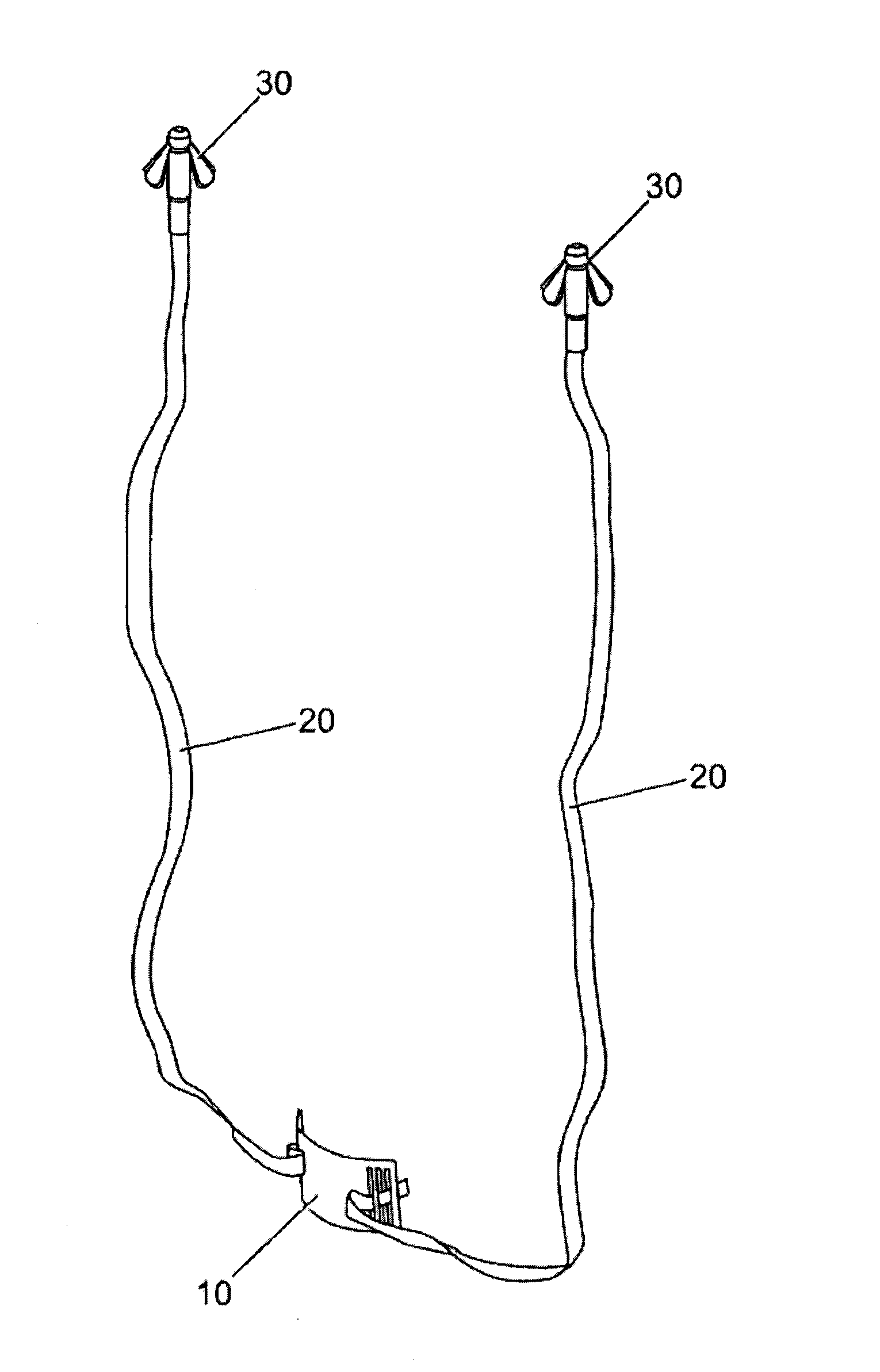
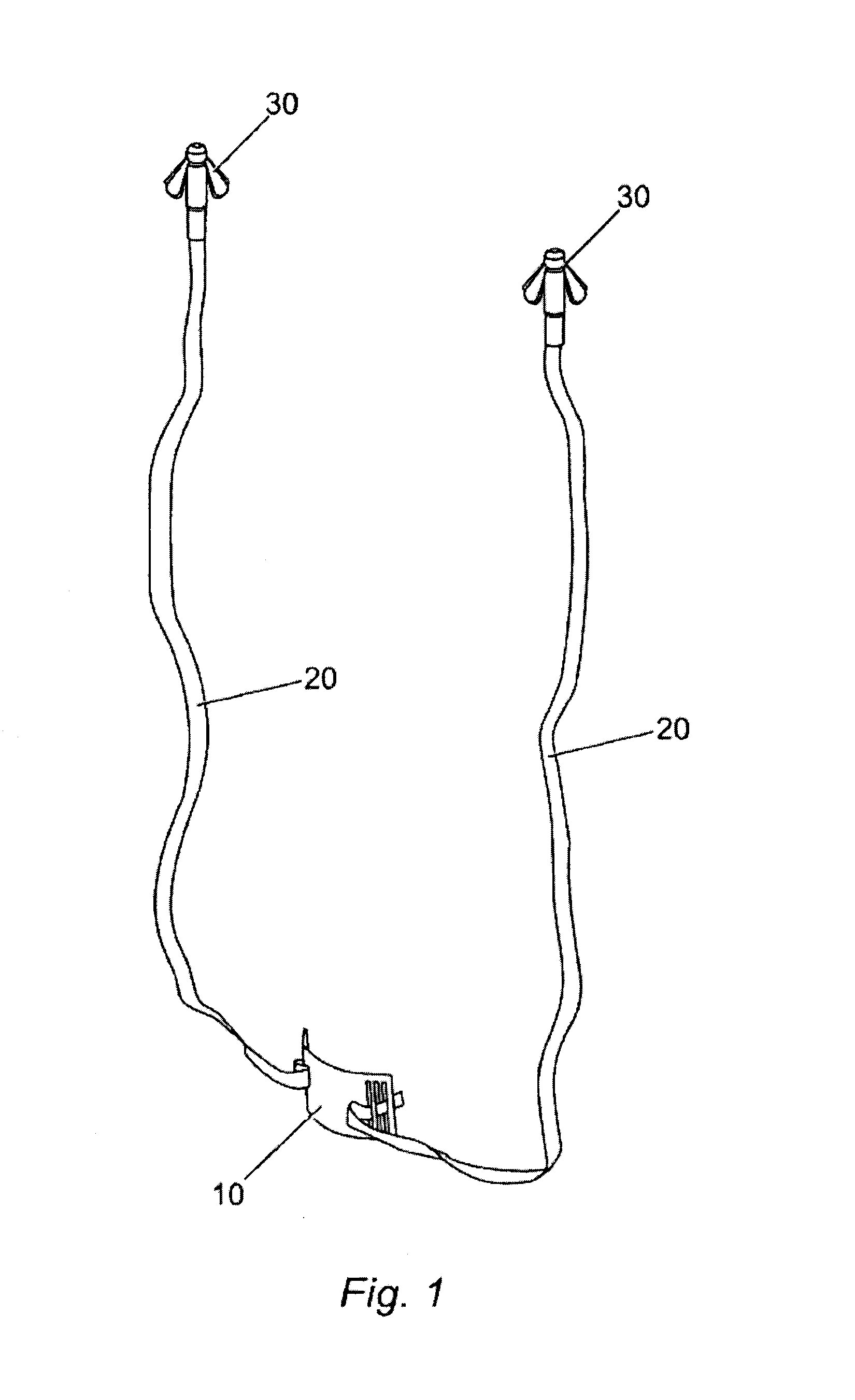
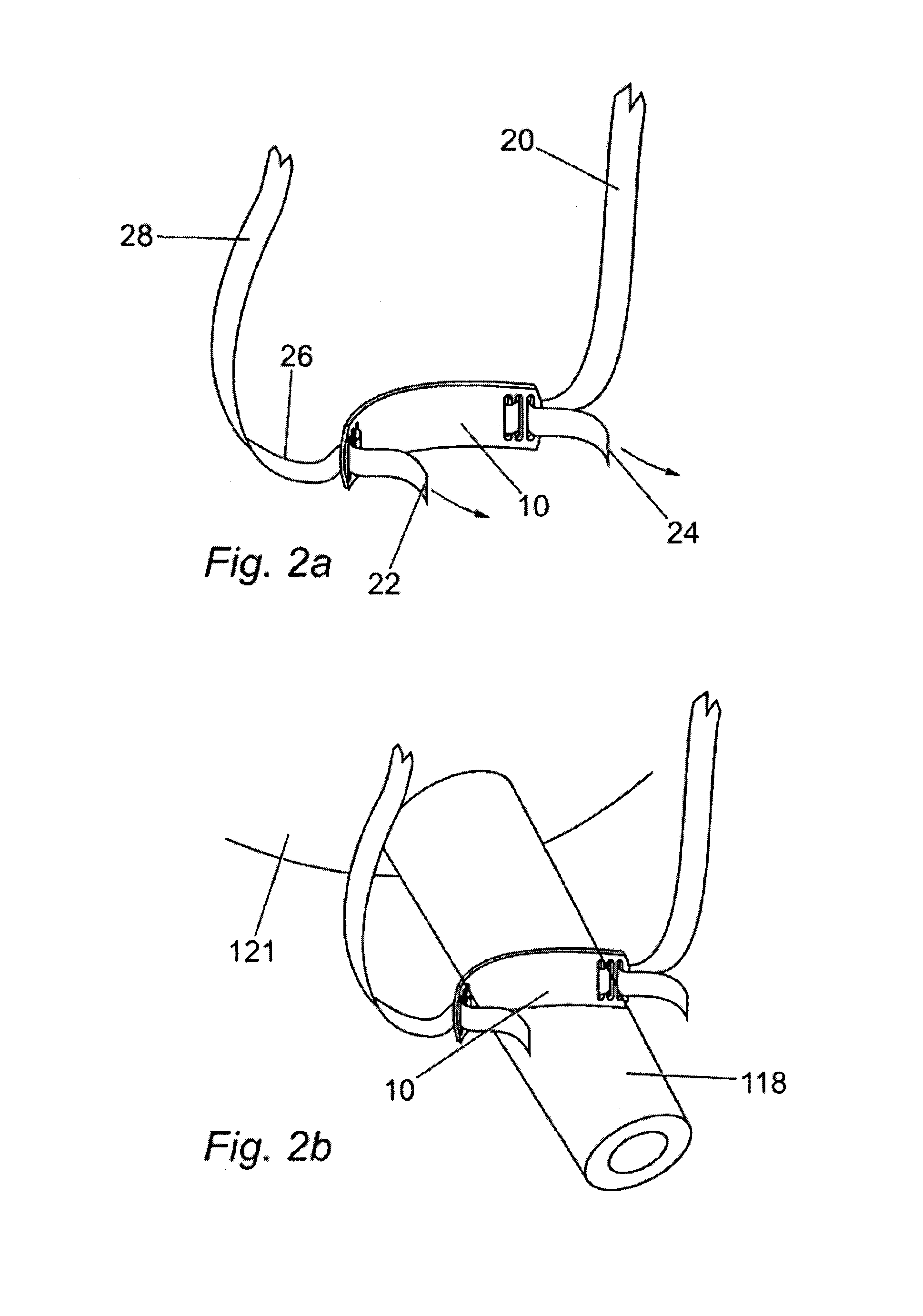
  • Method for fibrous anchoring of a pelvic support
  • Method for fibrous anchoring of a pelvic support
  • Method for fibrous anchoring of a pelvic support

Examples


first embodiment

[0604]In a first embodiment, retaining means 1920 are a plurality of projections 1922 extending laterally from the longitudinal axis of the implant. These projections 1922 are arranged along a substantial portion of the length of the fixing zone 196 such that when located in the tissues of the retropubic space they provide resistance at multiple levels within the fibro-fatty soft tissue and blood tissues of the para-urethral tunnel in a direction opposite to that in which the fixing zone 196 of the tape 192 is introduced into the tissues. This minimises movement of the tape out of the tissues of the retropubic space, even when a force is applied to the tape which acts to push or pull the tape out of the retropubic space.

[0605]Due to the multiple layers of fixation that can be achieved using the plurality of retaining means 1920 along a substantial length of the fixing zone 196 it is not necessary to insert the fixing zone through the rectus sheath 1944. This of significant advantage...

second embodiment

[0607]In a further second embodiment of the implant as shown in FIG. 32c, the implant further comprises resilient zones 197 interposed between the fixing zone and the supporting zone 194.

[0608]The two resilient zones 197 may comprise a geometric design of several strip portions conjoined at a first end to the supporting means and at a second opposite end to fixing means on the implant.

[0609]When not under tension these strip portions of tape material are bow shaped and are arranged such that they form a series of alternate and side by side convex and concave strips arranged in substantially the same plane as the tape.

[0610]On application of an extending force of up to 3N to the tape along its length, the tape can show 2-3 mm of extension, as the bowshaped portions of the tape are pulled into straight strips, the ends of the bowshaped strips being brought together, enabling extension of the tape. The movement of the tape from the resting bowshape into the tensioned straight strips of...


PUM

PropertyMeasurementUnit
forceaaaaaaaaaa
forceaaaaaaaaaa
lengthaaaaaaaaaa

Abstract

A method for supporting a urethra of a patient includes making an incision on an upper wall of a vagina of the patient and inserting a first end of a surgical implant through the incision and on a first side of a urethra of the patient. The first end of the surgical implant has a first fixing zone with a retaining portion that is formed of a fiber entanglement and a mesh.

Description

CROSS-REFERENCE TO RELATED APPLICATIONS[0001]This application is a continuation of U.S. patent application Ser. No. 11 / 324,028, filed Dec. 30, 2005, which is a continuation-in-part of U.S. patent application Ser. No. 10 / 510,488, filed Mar. 28, 2005, now abandoned, which is a U.S. national stage application of International Patent Application No. PCT / GB03 / 01573, filed Apr. 11, 2003, which claims priority to and the benefit of U.S. Provisional Patent Application No. 60 / 393,969, filed Jul. 5, 2002, and Great Britain Patent Application No. 0208359.0, filed Apr. 11, 2002. This application claims priority to each of the foregoing applications and incorporates each of the foregoing applications herein by reference, in their entireties and for all purposes. This application incorporates each of the following applications herein by reference, in their entireties and for all purposes: U.S. patent application Ser. No. 11 / 199,061, filed Aug. 8, 2005, issued as U.S. Pat. No. 7,789,821 on Sep. 7,...

Claims


Application Information

Patent Timeline
Patent Type & Authority Applications(United States)
IPC IPC(8): A61F2/02
CPCA61B17/00491Y10T29/49826A61B17/0469A61B17/06066A61B17/06109A61B19/54A61B2017/00805A61B2017/0409A61B2017/0412A61B2017/0417A61B2017/0427A61B2017/0464A61F2/0045A61F2220/0016A61F2250/0031A61F2250/0051A61F2/0063A61B17/0401A61B17/3468A61B90/39A61F2002/0072
Inventor BROWNING, JAMES
Owner COLOPLAST AS
Why Eureka
Try Eureka