
Impedance Mediated Power Delivery for Electrosurgery

a technology of impedance and power delivery, applied in the field of electrosurgery, can solve the problems of thermal damage and defective sealing, and achieve the effect of avoiding thermal damage, defective sealing and thermal damag

Active Publication Date: 2011-09-29
AESCULAP AG
View PDF105 Cites 21 Cited by
  • Summary
  • Abstract
  • Description
  • Claims
  • Application Information

AI Technical Summary

Benefits of technology

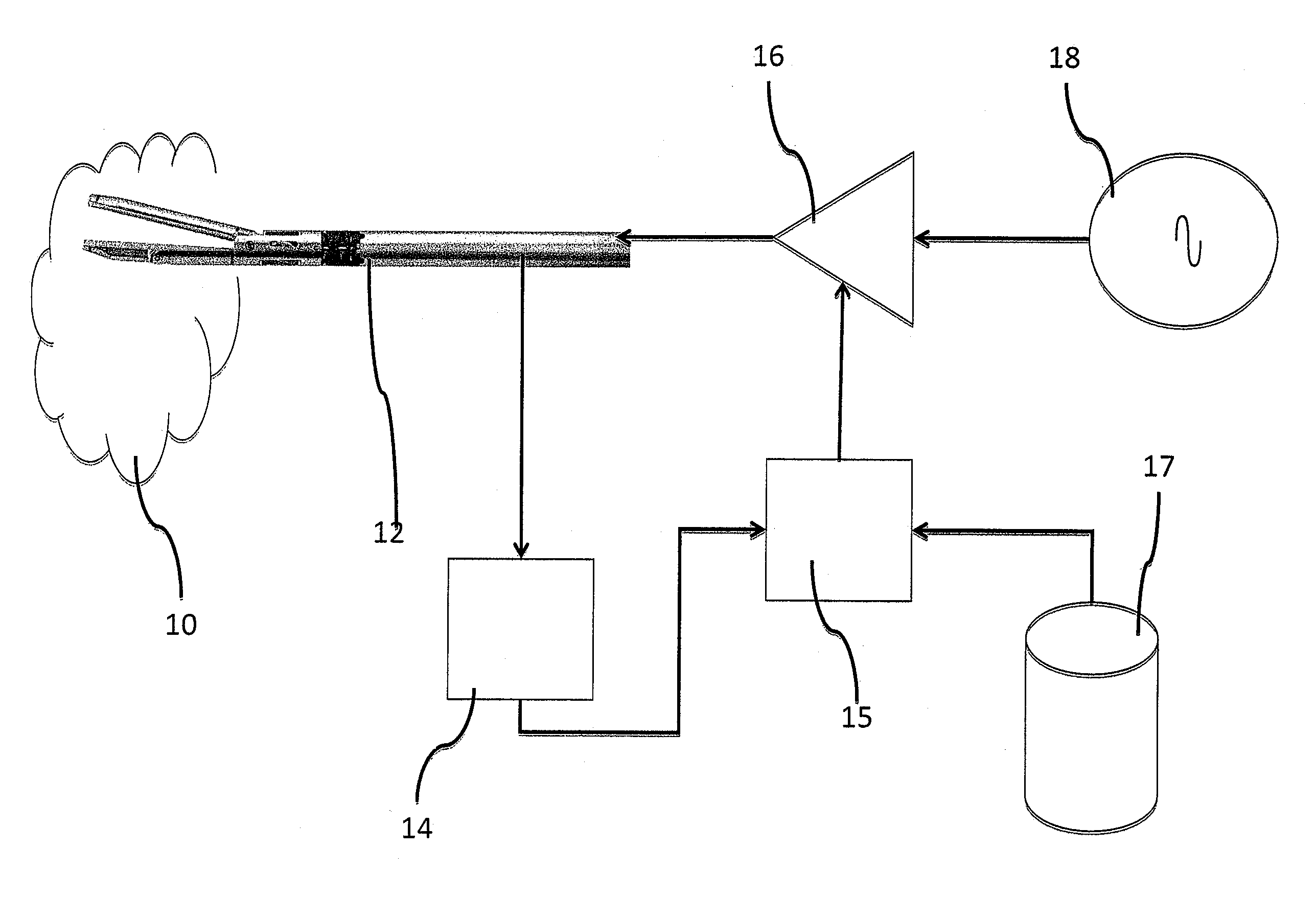
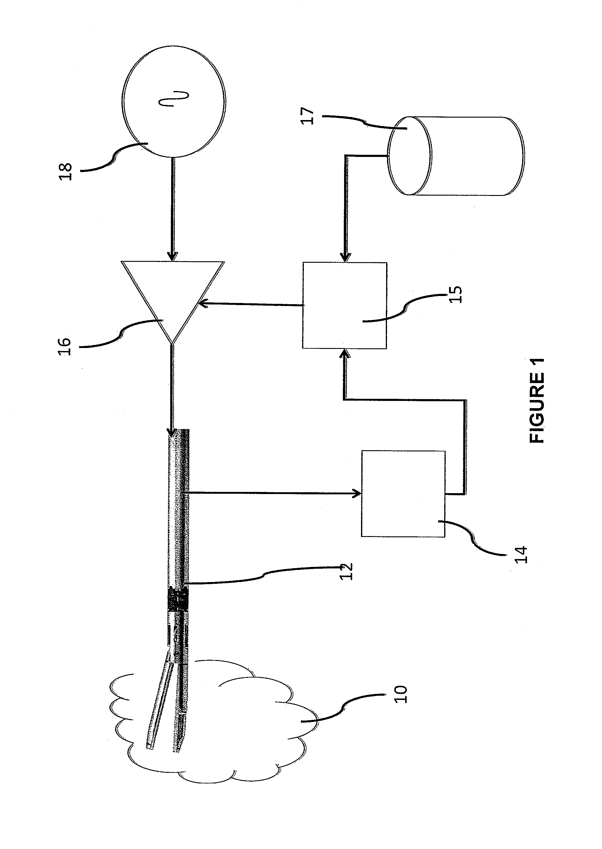
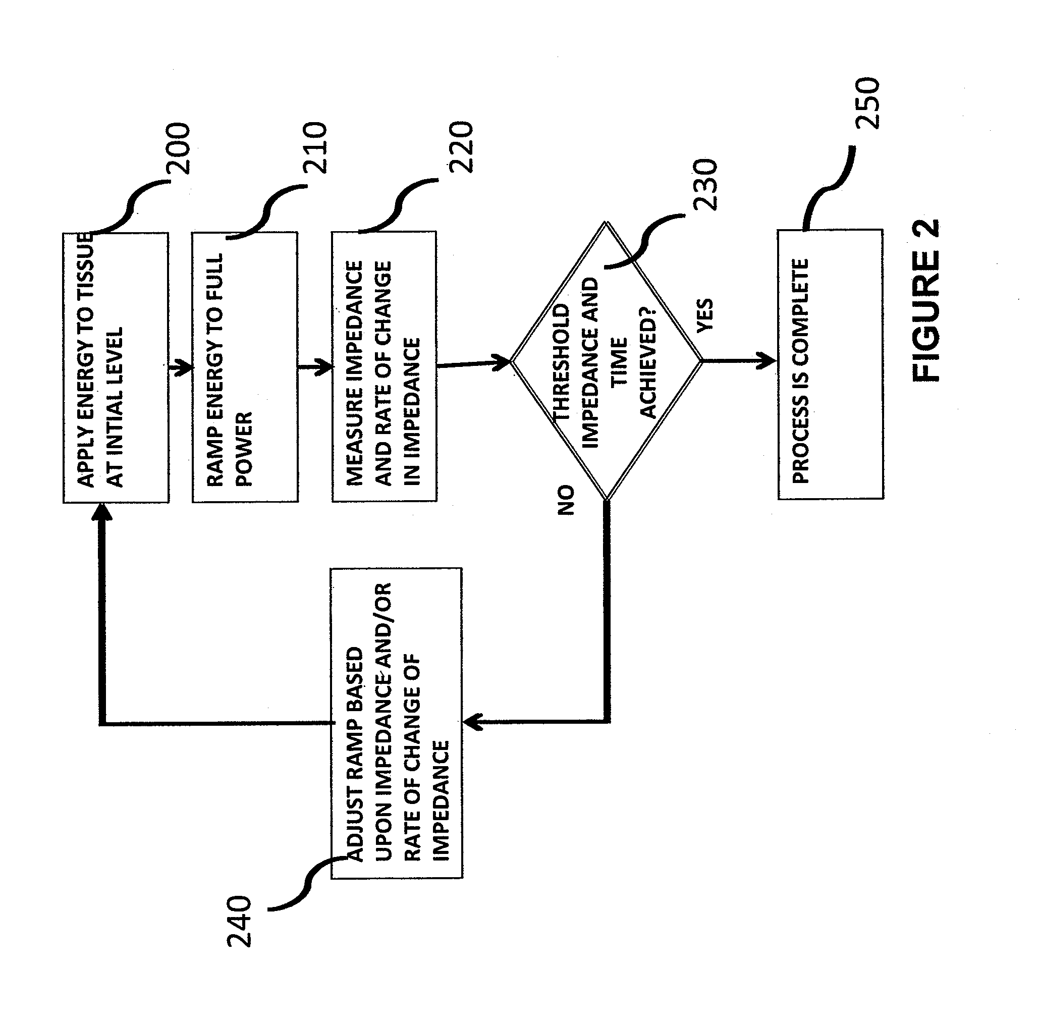
[0011]An embodiment of the invention provides an electrosurgical technique that addresses such issues as thermal damage to the tissue, partial coverage of the electrodes of the electrosurgical device by tissue, thin tissue, and defective sealing. This improvement is accomplished by use of an adaptive algorithm that monitors, inter alia, the rate of tissue impedance change. An aspect of the invention thus examines impedance levels achieved within a specific timeframe to determine an impedance ramp and / or slope rate, which indicates the rate at which the target tissue is undergoing a phase or state change and, thus, indicates tissue processing. The level of electrosurgical energy applied to the target tissue is adjusted in real time in accordance with such rate of impedance change. This approach, in effect, applies the energy at levels that allow tissue phase or state change to occur in an optimum fashion, for example allowing moisture to escape from the tissue slowly, and thus avoid thermal damage. As a result, such undesired results as thermal damage and defective sealing are mitigated.

Problems solved by technology

As a result, such undesired results as thermal damage and defective sealing are mitigated.

Method used


Image

  • Impedance Mediated Power Delivery for Electrosurgery
  • Impedance Mediated Power Delivery for Electrosurgery
  • Impedance Mediated Power Delivery for Electrosurgery

Examples


examples

Modified Power Delivery (Mitigation for Thermal Spread)

[0036]RF energy is delivered to the target tissue in multiple pulses of energy. The length of each pulse is defined as the RF Pulse Duration and the maximum number of pulses allowed for each seal is defined as the Max. RF Pulse Count. See FIG. 6.

Method:

[0037]1. The first RF pulse for a seal starts at a power level defined as the RF Setpoint Start Value. See FIG. 6.

[0038]2. The RF power level is then increased from the RF Setpoint Start Value by a rate defined as the RF Setpoint Ramp and / or slope rate until the power level reaches the upper level defined as the RF Setpoint End Value. The RE power level remains at this value until the end of the pulse time is reached. See FIG. 6.

[0039]3. At the end of each pulse, the tissue impedance value is calculated and recorded as the RF Pulse End Impedance and the power levels are then set to zero. See FIGS. 6 and 7.

[0040]4. For all pulses subsequent to the first, the following evaluations a...


PUM


Abstract

An adaptive algorithm monitors, inter alia, the rate of tissue impedance change during an electrosurgical procedure. Impedance levels achieved within a specific timeframe are examined to determine an impedance ramp and / or slope rate, which indicates the rate at which a target tissue is undergoing a phase or state change and, thus, indicates a desired rate of tissue processing. The level of electrosurgical energy applied to the target tissue is adjusted in real time in accordance with such rate of impedance change and / or by predetermined values. Energy is thus applied to the target tissue at levels that allow tissue phase or state change to occur in an optimum fashion, for example allowing moisture to escape from the tissue slowly, and thus avoid thermal damage. As a result, such undesired results as thermal damage and defective sealing are mitigated. Another embodiment determines impedance achieved within a specific interval and adjusts the electrosurgical energy applied to the tissue after a threshold impedance has been maintained or exceeded for a predetermined interval. A further aspect of the invention provides mitigation during processing for partial tissue coverage of device electrodes and / or for thin tissue.

Description

BACKGROUND OF THE INVENTION[0001]1. Technical Field[0002]The invention relates to electrosurgery. More particularly, the invention relates to impedance mediated power delivery for electrosurgery.[0003]2. Description of the Prior Art[0004]The state of the art of electrosurgery is well summarized in U.S. patent publication no. 2009 / 0157071 (Wham et al), where it is stated:[0005]“Electrosurgery involves application of high radio frequency electrical current to a surgical site to cut, ablate, or coagulate tissue. In monopolar electrosurgery, a source or active electrode delivers radio frequency energy from the electrosurgical generator to the tissue and a return electrode (e.g., a return pad) carries the current back to the generator. In monopolar electrosurgery, the source electrode is typically part of the surgical instrument held by the surgeon and applied to the tissue to be treated. The patient return electrode is placed remotely from the active electrode to carry the current back ...

Claims


Application Information

Patent Timeline
Patent Type & Authority Applications(United States)
IPC IPC(8): A61B18/12
CPCA61B18/1206A61B18/1445A61B2018/00589A61B2018/00595A61B18/18A61B2018/00642A61B2018/00678A61B2018/00702A61B2018/00875A61B2018/0063
Inventor KOSS, TIMTAIMISTO, MIRIAM H.VARNER, ROSEANNE
Owner AESCULAP AG
Learn More