
Full Wavefield Inversion Using Time Varying Filters

a filter and wavefield technology, applied in the field of numerical inversion of seismic data, can solve the problems of many minima of objective functions, increased computation cost, and many wrong solutions, so as to reduce the number of iterations and reduce the cost and compute time.

Active Publication Date: 2011-09-29
EXXONMOBIL UPSTREAM RES CO
View PDF99 Cites 57 Cited by
  • Summary
  • Abstract
  • Description
  • Claims
  • Application Information

AI Technical Summary

Benefits of technology

[0027]The present invention is an improved method for reducing the accuracy requirements on the starting model when performing local objective function optimization.SUMMARY OF THE INVENTION
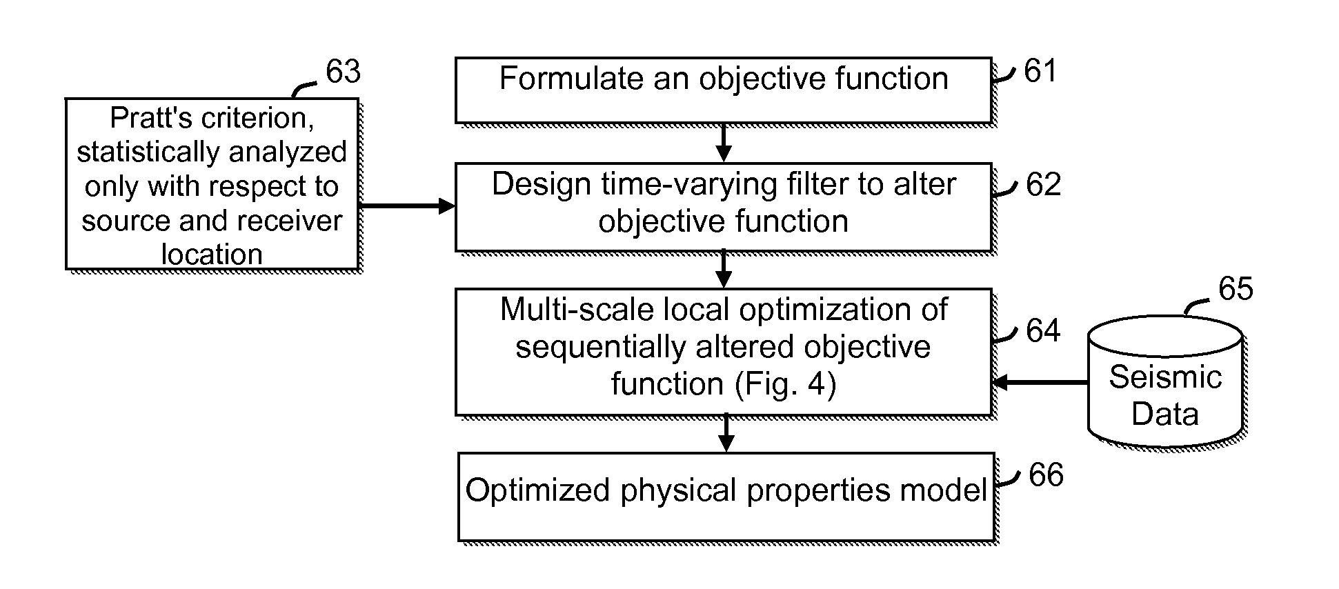
[0028]The present inventive method is applicable to any inversion based on a wave simulator, such as acoustic or seismic inversion. In one of its aspects, the invention is a specific method for altering the objective function which will, for a given inaccuracy in the starting model, reduce the number of iterations needed to find the global minimum. Reducing the number of iterations will correspondingly reduce cost and compute time. The alteration comprises incorporating a time varying filter into the objective function. This filter is chosen so that some statistical measure of the traveltime difference between the measured and computed data is less than some fraction (usually one quarter) of the dominant period of the data. This implies that the filter be a high-cut filter. The filter is further chosen such that the high-cut frequency of this filter decreases with increasing traveltime, making it a time-varying filter.

Problems solved by technology

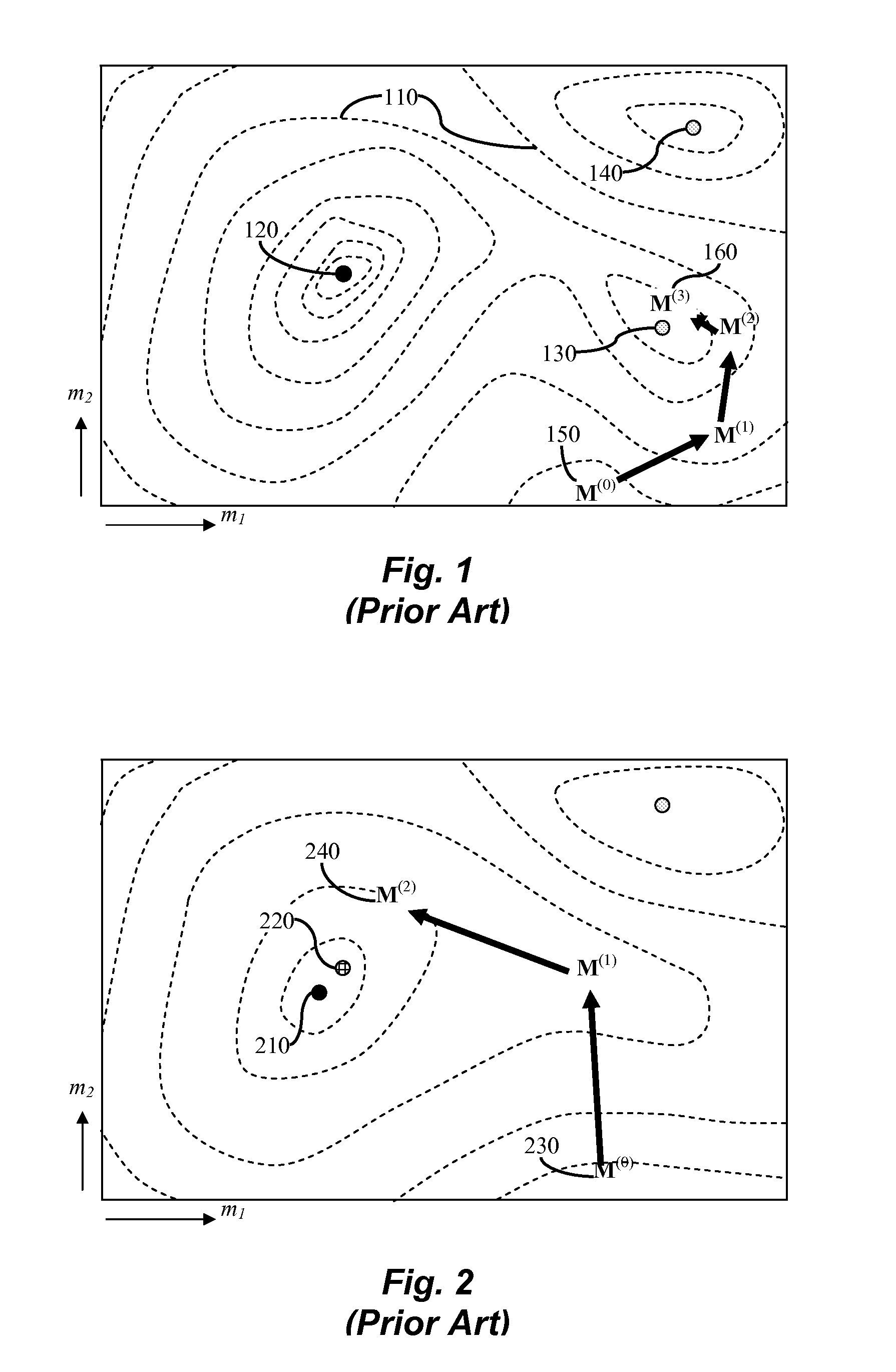
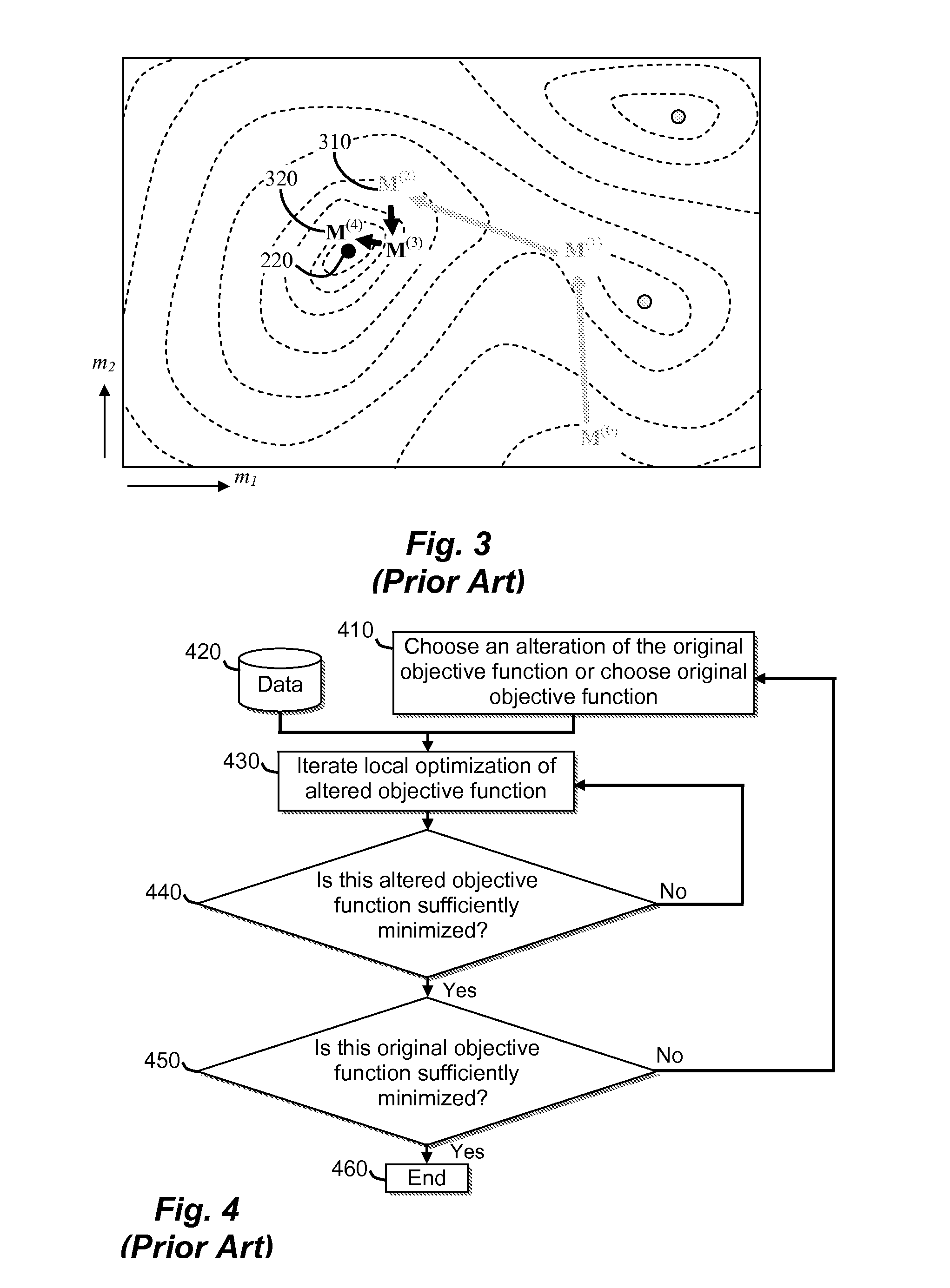
Unfortunately, the objective function often has many minima, not just one minimum corresponding to the solution model.
Thus, the wrong solution is produced no matter how much effort is expended on iteration.
Iterative inversion usually produces a more accurate model than non-iterative inversion, but is much more expensive to compute.
Global methods are more likely to converge to the correct solution than local methods, but are too expensive to apply to large scale inversion problems having many model parameters.
When N is very large (roughly more than a thousand), this computation can be extremely time consuming if it had to be performed for each individual model parameter.

Method used


Image

  • Full Wavefield Inversion Using Time Varying Filters
  • Full Wavefield Inversion Using Time Varying Filters
  • Full Wavefield Inversion Using Time Varying Filters

Examples


example 1

[0047]This implies that this particular time varying filter performs no filtering at time zero. The off-diagonal elements increase for increasing rows in the sub-matrix, implying that the high cut frequency of this time varying filter decreases with increasing time. Notice that the traveltime error could be viewed as functions of the source or receiver. In this case, this method could be applied in a more general manner than just a simple time varying filter. For example:[0048]1. The traveltime error is often not just a function of traveltime, but is also often a function of the offset between the source and the receiver. If this is the case, it would be advantageous to use different time-varying filters for different source receiver offsets. As iteration proceeds the filter would be relaxed as the accuracy of the model increases.[0049]2. The traveltime error is often a function of the time dip of the data in the source and / or receiver domain. This can happen because steep time dips...


PUM


Abstract

An improved method for reducing the accuracy requirements on the starting model when performing multi-scale inversion of seismic data (65) by local objective function optimization (64). The different scales of inversion are brought about by incorporating a low-pass filter into the objective function (61), and then decreasing the amount of high-frequency data that is filtered out from one scale to the next. Moreover, the filter is designed to be time varying, wherein the filter's low-pass cutoff frequency decreases with increasing traveltime of the seismic data being filtered (62). The filter may be designed using Pratt's criterion for eliminating local minima, and performing averages (or other statistical measure) of the period and the traveltime error only with respect to source and receiver location but not traveltime (63).

Description

CROSS-REFERENCE TO RELATED APPLICATION[0001]This application claims the benefit of U.S. Provisional Patent Application 61 / 318,561, filed Mar. 29, 2010, entitled FULL WAVEFIELD INVERSION USING TIME VARYING FILTERS, the entirety of which is incorporated by reference herein.FIELD OF THE INVENTION[0002]The invention relates generally to the field of numerical inversion of seismic data to infer elastic parameters of the propagating medium. More particularly, the invention is a method for reducing the accuracy requirements on the starting model when performing local objective function optimization in inversions such as seismic data inversion.BACKGROUND OF THE INVENTION[0003]Inversion [see, for example, Tarantola, 1984] attempts to find a model that optimally explains observed data. Local inversion methods that minimize the value of an objective function that measures the difference between simulated and observed data, are often the only practical means of solving an inversion problem for ...

Claims


Application Information

Patent Timeline
IPC IPC(8): G06F17/10G06F40/00
CPCG01V1/282G06F7/544G06F11/3452G06F11/3457G06F11/3608G06F17/10G06F17/16G06N5/04G06T17/05G06F16/29G06F30/20G06F30/3312G06F30/3323
Inventor KREBS, JEROME R.ANDERSON, JOHN E.
Owner EXXONMOBIL UPSTREAM RES CO
Learn More