Substrate treatment apparatus and substrate treatment method

a treatment apparatus and substrate technology, applied in the direction of chemistry apparatus and processes, cleaning using liquids, coatings, etc., can solve the problems of difficult to achieve the sufficient control of the atmosphere in the treatment chamber, and the inability to effectively reduce the internal space. , to achieve the effect of suppressing the contamination of the substrate holding/rotating uni

Active Publication Date: 2011-10-06
DAINIPPON SCREEN MTG CO LTD
View PDF2 Cites 62 Cited by
  • Summary
  • Abstract
  • Description
  • Claims
  • Application Information

AI Technical Summary

Benefits of technology

[0042]According to the inventive method, the treatment liquid adhering to the lid member can be washed away by spouting the cleaning liquid toward the lid member from the cleaning liquid spouting unit while rotating the lid member. The cleaning liquid supplied to the lid member receives a centrifugal force generated by the rotation of the lid member to move toward a peripheral portion of the lid member, and is supplied to the interior wall of the chamber body. Therefore, the treatment liquid adhering to the interior wall of the chamber body can be washed away. Thus, the entire interior wall of the seal chamber can be cleaned. Even during the rotation of the lid member, the inside of the seal chamber can be maintained in the sealed state by the function of the first liquid seal structure. Since the interior wall of the seal chamber defining a smaller internal space can be kept clean, the substrate can be properly treated in the internal space.
[0043]Further, the cleaning of the lid member, i.e., the cleaning of the inside of the seal chamber, is achieved with the substrate holding/rotating unit being located relative to the seal chamber at a lid cleaning position different from a liquid treatment position. The substrate holding/rotating unit is located closer to the lid member at

Problems solved by technology

However, it seems to be impossible to effectively reduce the internal space, because various components are disposed together in the treatment chamber.
This makes it impossible to effectively reduce the volume of the internal space of the treatment chamber, making it difficult to achieve

Method used


Image

  • Substrate treatment apparatus and substrate treatment method
  • Substrate treatment apparatus and substrate treatment method
  • Substrate treatment apparatus and substrate treatment method

Examples


Embodiment Construction

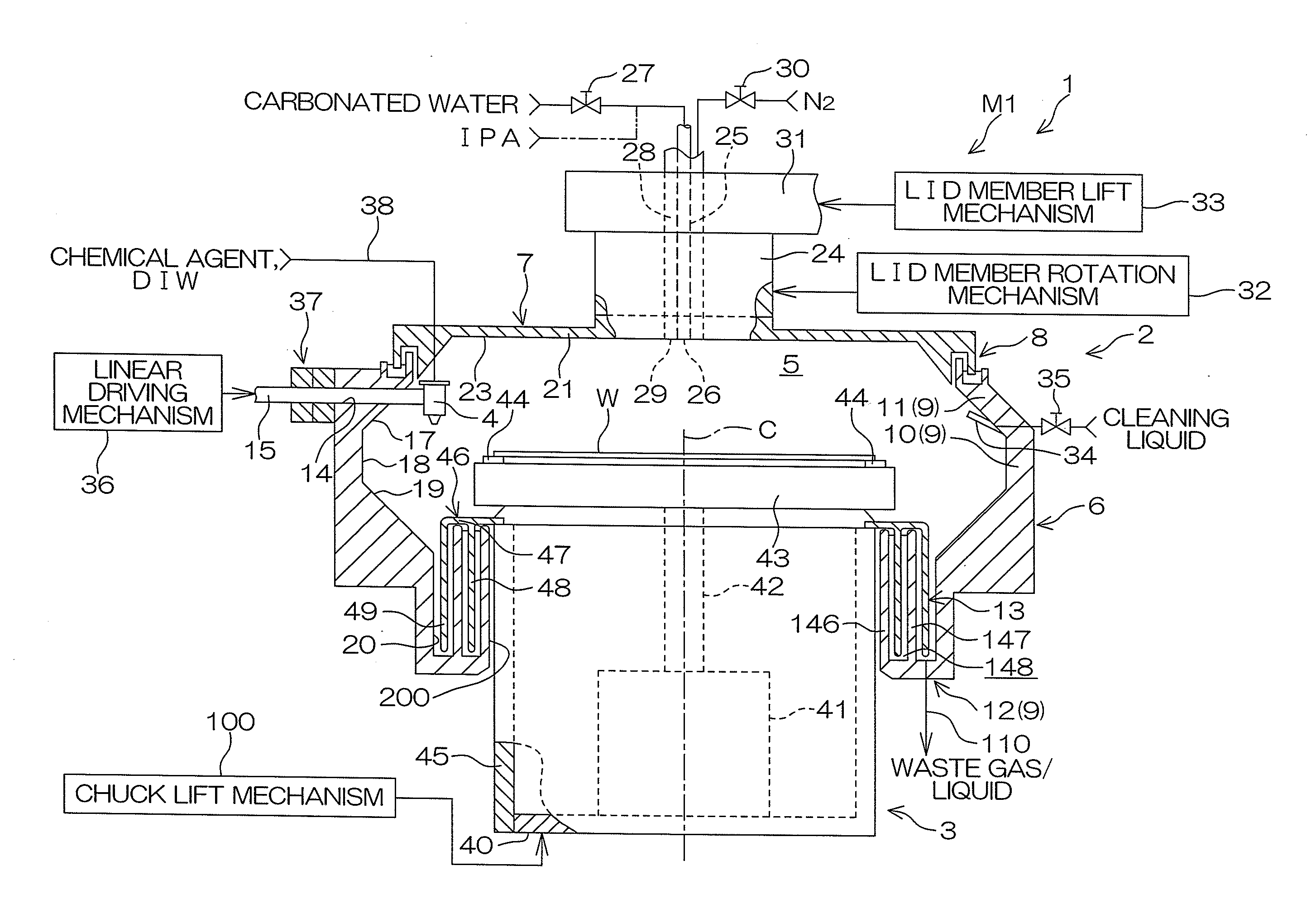
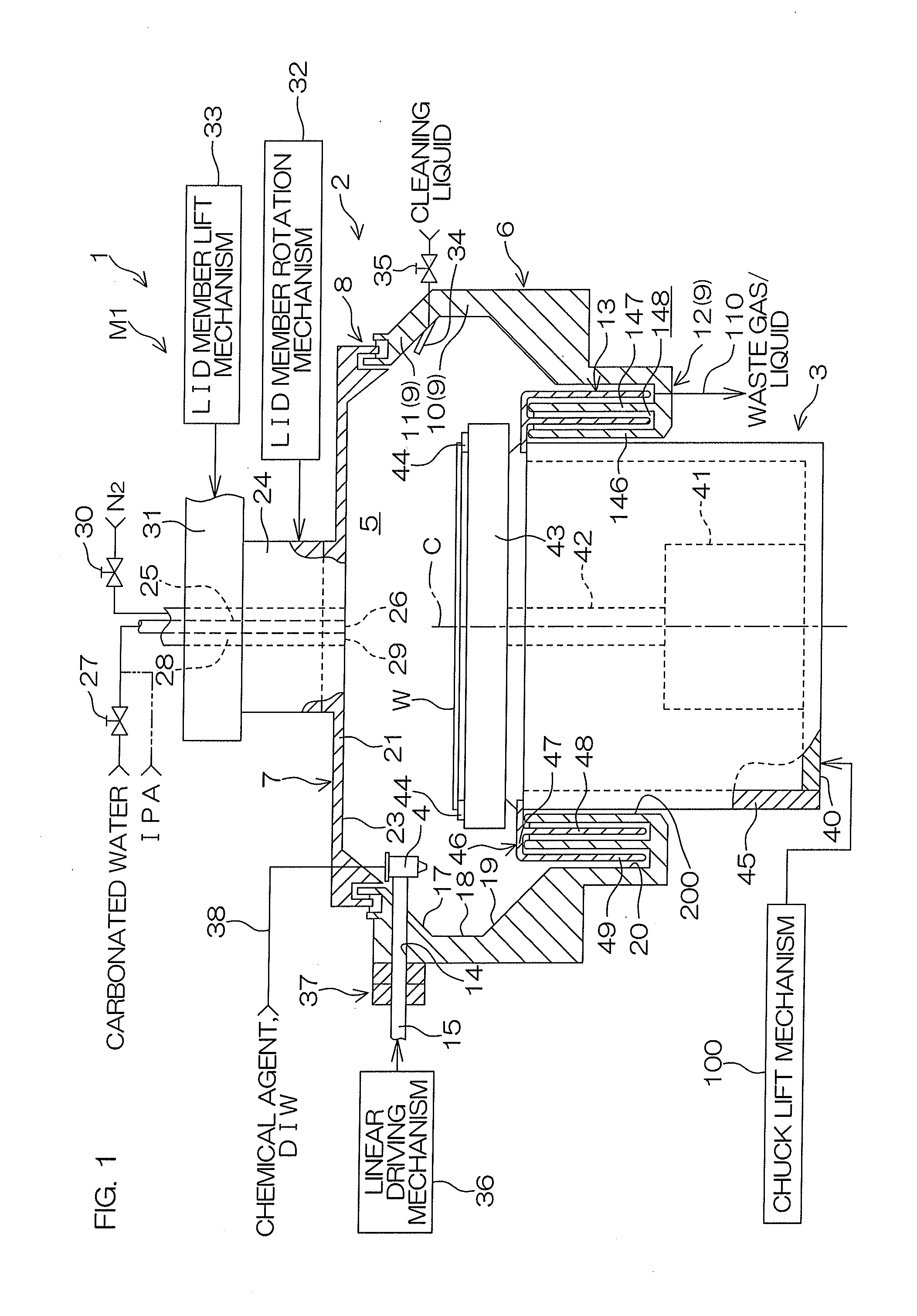
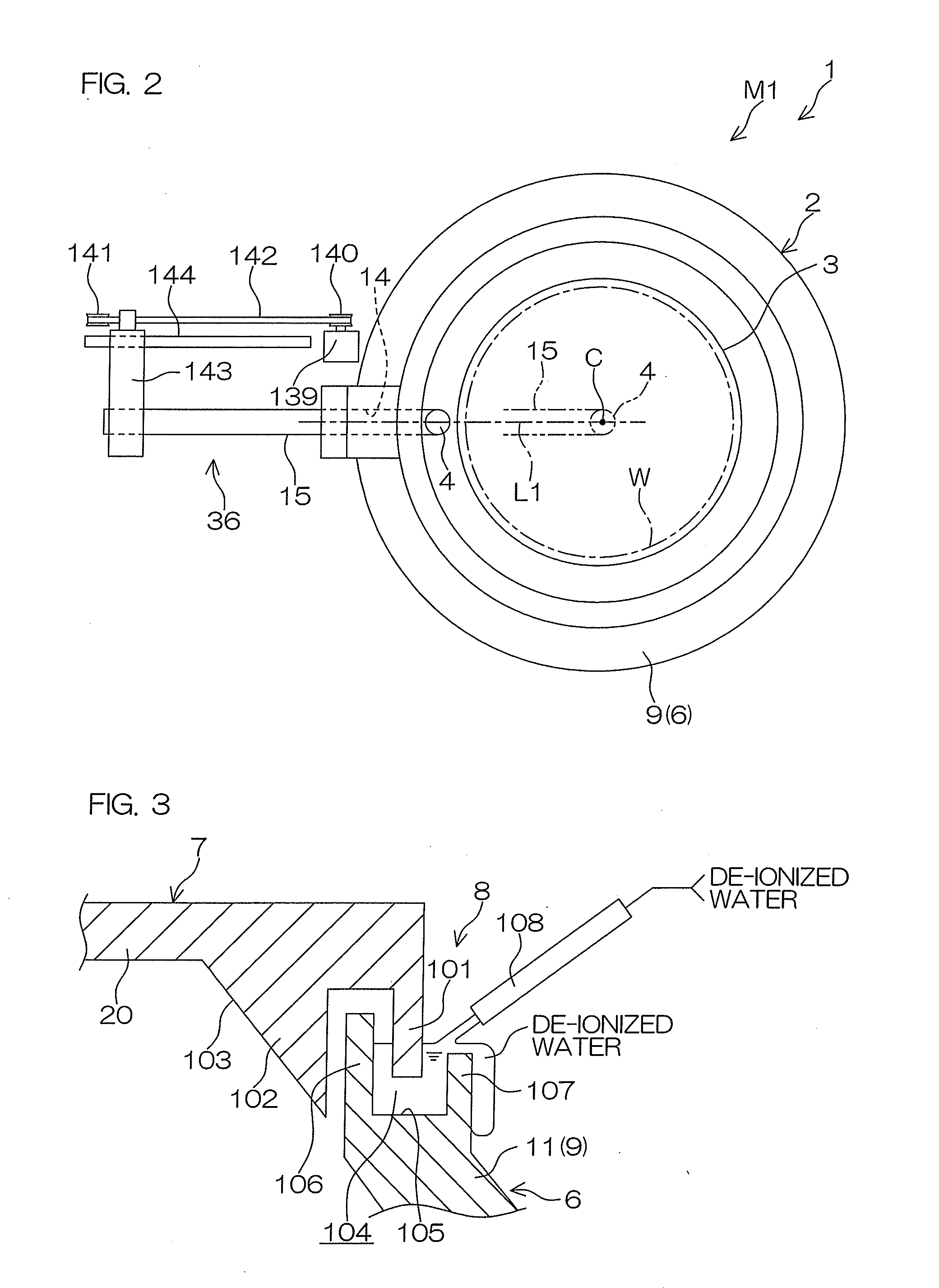
[0085]FIG. 1 is a schematic sectional view showing the construction of a substrate treatment apparatus 1. FIG. 2 is a schematic plan view for explaining the construction of the substrate treatment apparatus 1. In FIG. 2, components of the substrate treatment apparatus 1 related to a treatment liquid nozzle (treatment liquid supplying unit) 4 and a nozzle arm 15 are mainly shown, and an arrangement not directly related to these components are omitted.

[0086]The substrate treatment apparatus 1 is of a single substrate treatment type, which is adapted, for example, to perform a wafer cleaning process (e.g., a residual polymer removing process) on a front surface (major surface) of a round semiconductor wafer W (as an exemplary substrate, hereinafter referred to simply as “wafer W”) having a device formation region by using a diluted hydrofluoric acid solution as an exemplary chemical agent.

[0087]The substrate treatment apparatus 1 has a treatment module M1 for treating the wafer W. The ...


PUM

PropertyMeasurementUnit
Speedaaaaaaaaaa

Abstract

A substrate treatment apparatus is provided, which includes: a seal chamber including a chamber body having an opening, a lid member provided rotatably with respect to the chamber body and configured to close the opening, and a first liquid seal structure which liquid-seals between the lid member and the chamber body, the seal chamber having an internal space sealed from outside; a lid member rotating unit which rotates the lid member; a substrate holding/rotating unit which holds and rotates a substrate in the internal space of the seal chamber; and a treatment liquid supplying unit which supplies a treatment liquid to the substrate rotated by the substrate holding/rotating unit.

Description

BACKGROUND OF THE INVENTION[0001]1. Field of the Invention[0002]The present invention relates to a substrate treatment apparatus and a substrate treatment method for treating a substrate. Examples of the substrate to be treated include semiconductor wafers, glass substrates for liquid crystal display devices, substrates for plasma display devices, substrates for FED (Field Emission Display) devices, substrates for optical disks, substrates for magnetic disks, substrates for magneto-optical disks, substrates for photo masks, and substrates for solar cells.[0003]2. Description of Related Art[0004]In a semiconductor device production process, for example, a substrate such as a semiconductor wafer or a glass substrate for a liquid crystal display panel is treated with a chemical agent. For the treatment with the chemical agent, a substrate treatment apparatus of a single substrate treatment type is often used, which is adapted to treat a single substrate at a time. The substrate treatme...

Claims


Application Information

Patent Timeline
IPC IPC(8): C23F1/00C23F1/08
CPCH01L21/02063H01L21/67028H01L21/67051H01L21/67017H01L21/6719H01L21/76814B44C1/227H01L21/67126H01L21/302
Inventor HASHIZUME, AKIOAKANISHI, YUYAKAWAGUCHI, KENJIYAMAMOTO, MANABU
Owner DAINIPPON SCREEN MTG CO LTD
Why Eureka
Try Eureka