Locking mechanism for a seat belt

Inactive Publication Date: 2011-10-06
LEE KUO HAO
View PDF8 Cites 6 Cited by
  • Summary
  • Abstract
  • Description
  • Claims
  • Application Information

AI Technical Summary

Benefits of technology

The main objective of the invention is to allow muddy water, sand or dirt to fall out of the l

Problems solved by technology

However, if driven on sand, mud, or riverbeds, then it is possible that muddy water, sand or dirt might enter the locking mechanism.
Once sand or dirt enters the locking mechanism, the sand or dirt may accumulate on the mount (61) and sti

Method used


Image

  • Locking mechanism for a seat belt
  • Locking mechanism for a seat belt
  • Locking mechanism for a seat belt

Examples


Example

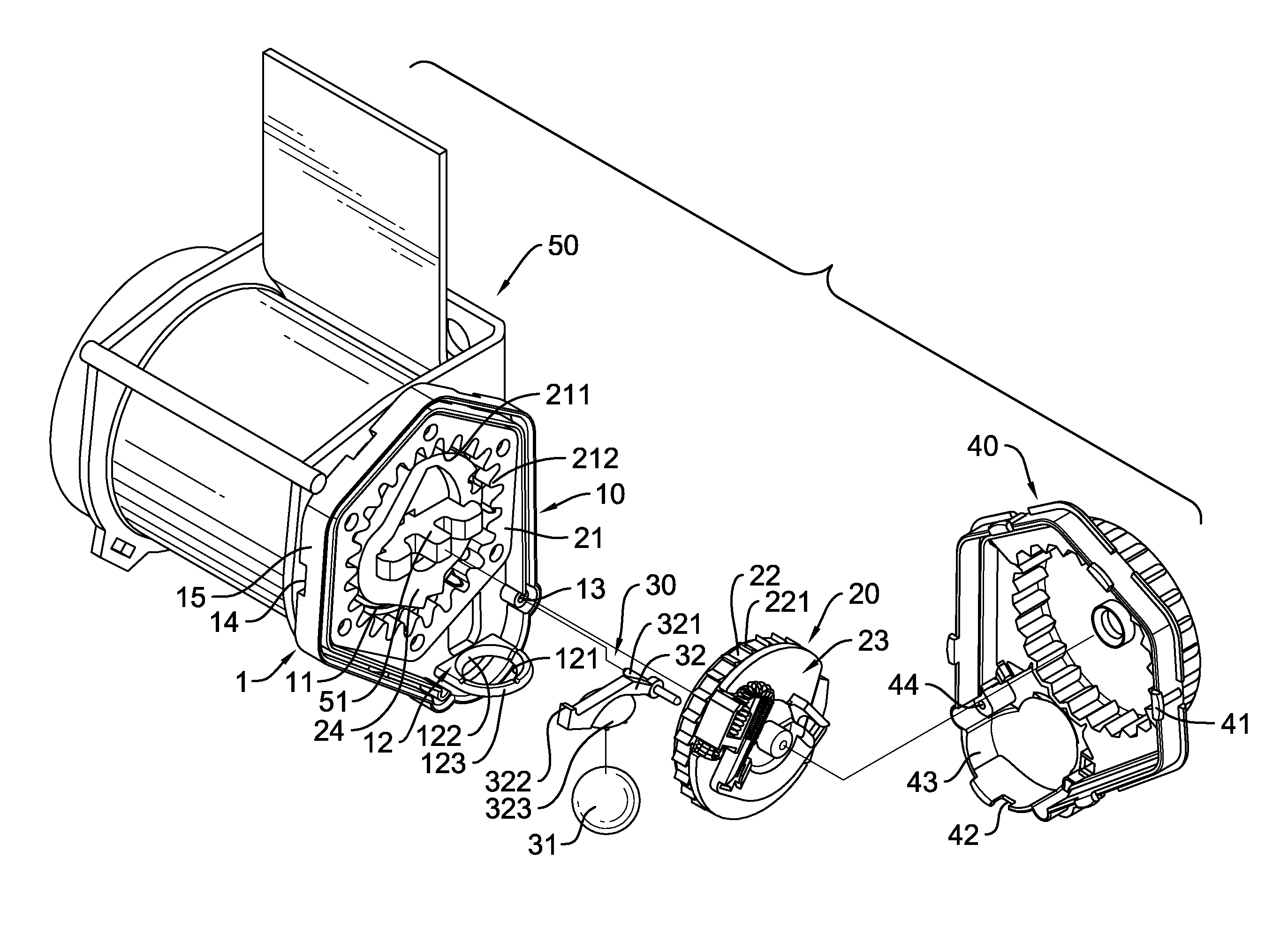
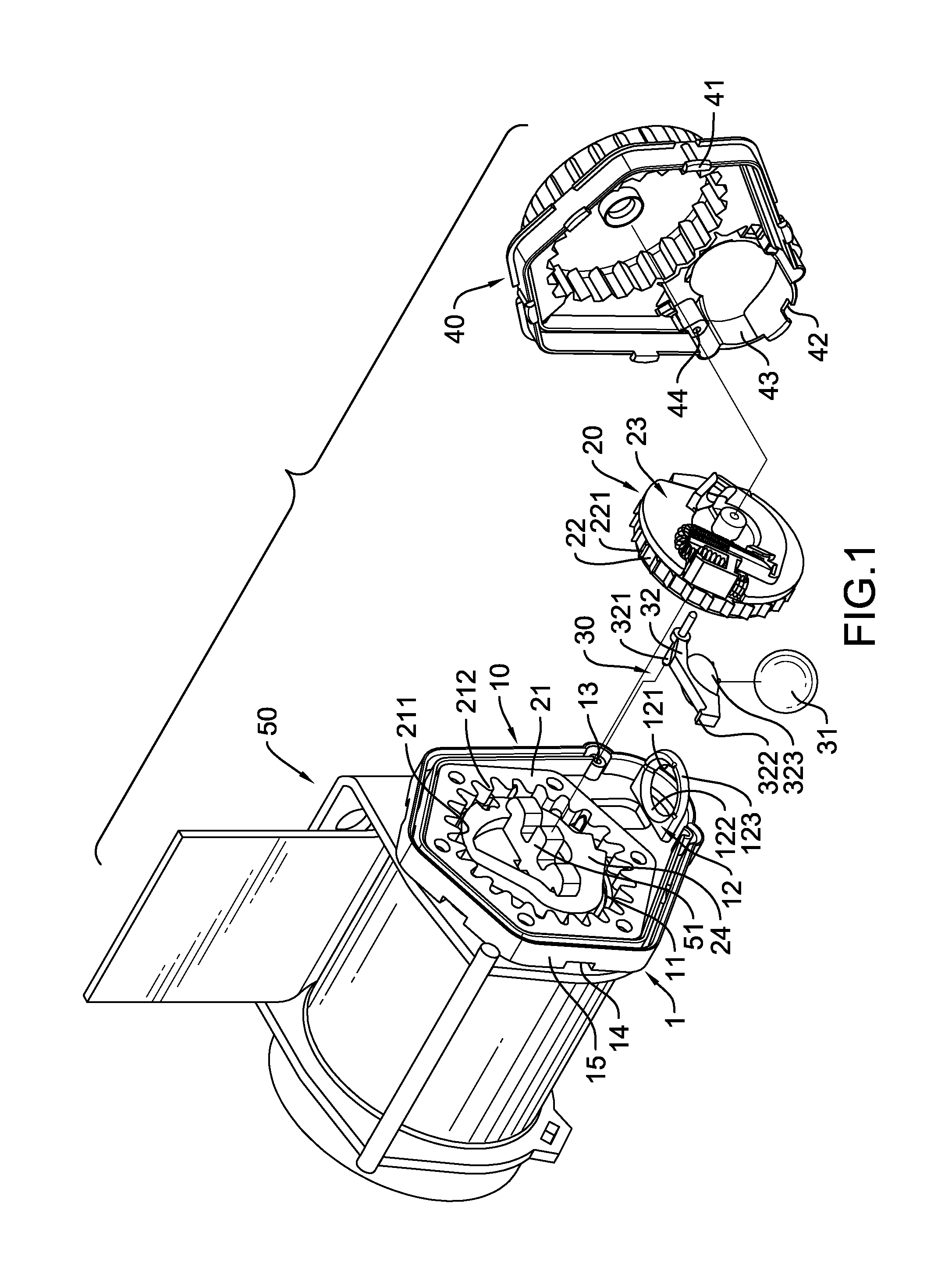
With reference to FIG. 1, a locking mechanism for a seat belt is mounted adjacent to a side of a retractor (50) having a shaft (51) protruding out of the retractor (50) and the locking mechanism is mounted around the shaft (51) and comprises a case (1), a locking set (20) and a sensor (30).

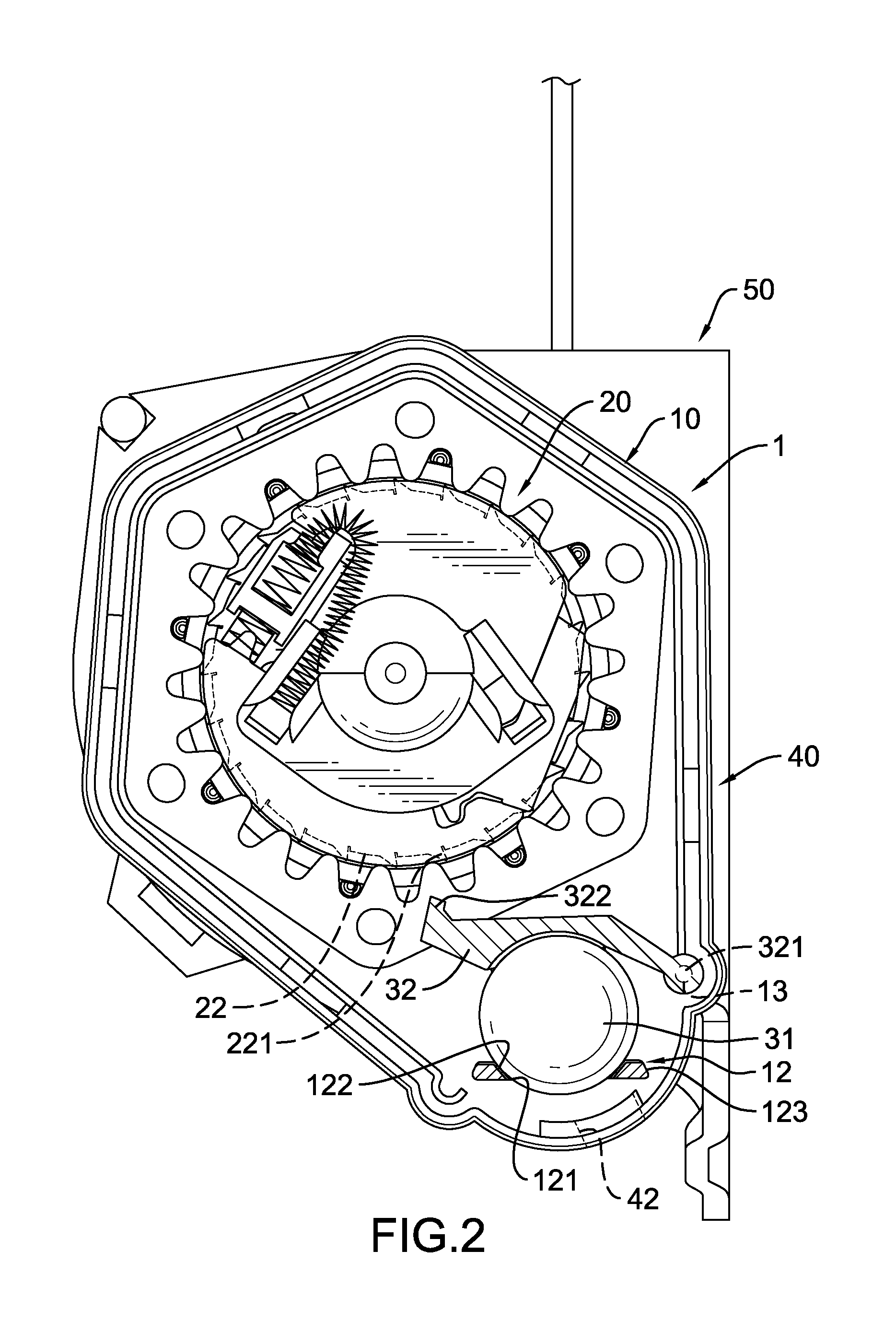
The case (1) is mounted adjacent to the side of the retractor (50) and has a bottom, a chamber defined inside the case (1), a side, a pivot hole (11), a flat support (12) and at least one opening (42), and may be composed of a base (10) with a lower segment and a lid (40). The side of the case (1) is adjacent to the side of the retractor (50) and may further be formed on the base (10). The pivot hole (11) is formed on the side of the base (1) and around the shaft (51) of the retractor (50).

With further reference to FIG. 5, the flat support (12) is attached inside the chamber and may be separately mounted or integrally formed on the lower segment of the base (10) and has a flat body, a top surface ...


PUM


Abstract

A locking mechanism for a seat belt has a case, a locking set and a sensor. The case is mounted adjacent to a side of a retractor having a shaft and the case is mounted around the shaft and has a flat support inside the case and at least one opening being formed on the bottom. The flat support has at least one hole formed therethrough. The locking set is mounted on the shaft. The sensor has a steel ball and a rod. The steel ball is detachably disposed on the flat support and the rod is pivotally mounted in the case and is disposed on the steel ball. If muddy water, sand or dirt enters the locking mechanism, muddy water, sand or dirt can fall through the at least one hole of the flat support and the at least one opening thus avoiding muddy water, sand or dirt affecting the locking mechanism.

Description

BACKGROUND OF THE INVENTION1. Field of the InventionThe present invention relates to a locking mechanism for a seat belt, more particularly to a locking mechanism that stops the belt from spooling out when the belt is pulled fast or the vehicle experiences a sudden change in velocity. This particular invention allows muddy water, sand or dirt to fall out of or exit the mechanism and thus prevents the accumulation from sticking to the mechanism and unpredictable dangers.2. Description of Related ArtWith reference to the FIG. 6, a conventional locking mechanism for a seat belt has a case, a locking set (70), a sensor (80) and a lid. The case is hollow and composed of a base (60) and a lid. The base (60) has a lower segment and a mount (61) mounted on the lower segment. The locking set (70) has a ratchet wheel (71) mounted on a shaft of an inertia reel and an inertia plate mounted on the ratchet wheel (71). The sensor (80) has a steel ball (81) disposed detachably on the mount (61) and...

Claims


Application Information

Patent Timeline
IPC IPC(8): B60R22/40B60R22/36
CPCB60R22/40
Inventor LEE, KUO-HAO
Owner LEE KUO HAO
Why Eureka
Try Eureka