Vision Equipment Comprising an Optical Strip with a Controlled Coefficient of Light Transmission

a technology of optical strips and control coefficients, which is applied in the direction of static indicating devices, optical radiation measurement, instruments, etc., can solve the problems of disrupting the pilot, the use of vision equipment inside the cockpit is problematic, and the task of the pilot becomes particularly complex, so as to improve the ease of use and improve the safety of the flight. , the effect of improving the quality of the imag

Active Publication Date: 2011-10-06
BEIJING VOYAGER TECH CO LTD
View PDF14 Cites 30 Cited by
  • Summary
  • Abstract
  • Description
  • Claims
  • Application Information

AI Technical Summary

Benefits of technology

[0017]The vision equipment according to the invention improves the quality of display of the images by an automatic management of the contrast depending on the conditions of use (ambient luminosity, orientation of the gaze of the user). Moreover, the independent control of the coefficient of light transmission of each field zone allows additional functionalities of the display surface. For example, the upper zone of the optical strip is used as a sun shade by controlling the coefficient of light transmission to a l...

Problems solved by technology

The task of the pilot becomes particularly complex during flight phases at low altitude to monitor the obstacles and the terrain and, in the case of a tactical mission, to monitor moving objects.
The use of the vision equipment inside a cockpit is problematical for several reasons.
The visibility of this daytime image requires a strong contrast which the lower...

Method used


Image

  • Vision Equipment Comprising an Optical Strip with a Controlled Coefficient of Light Transmission
  • Vision Equipment Comprising an Optical Strip with a Controlled Coefficient of Light Transmission
  • Vision Equipment Comprising an Optical Strip with a Controlled Coefficient of Light Transmission

Examples


first embodiment

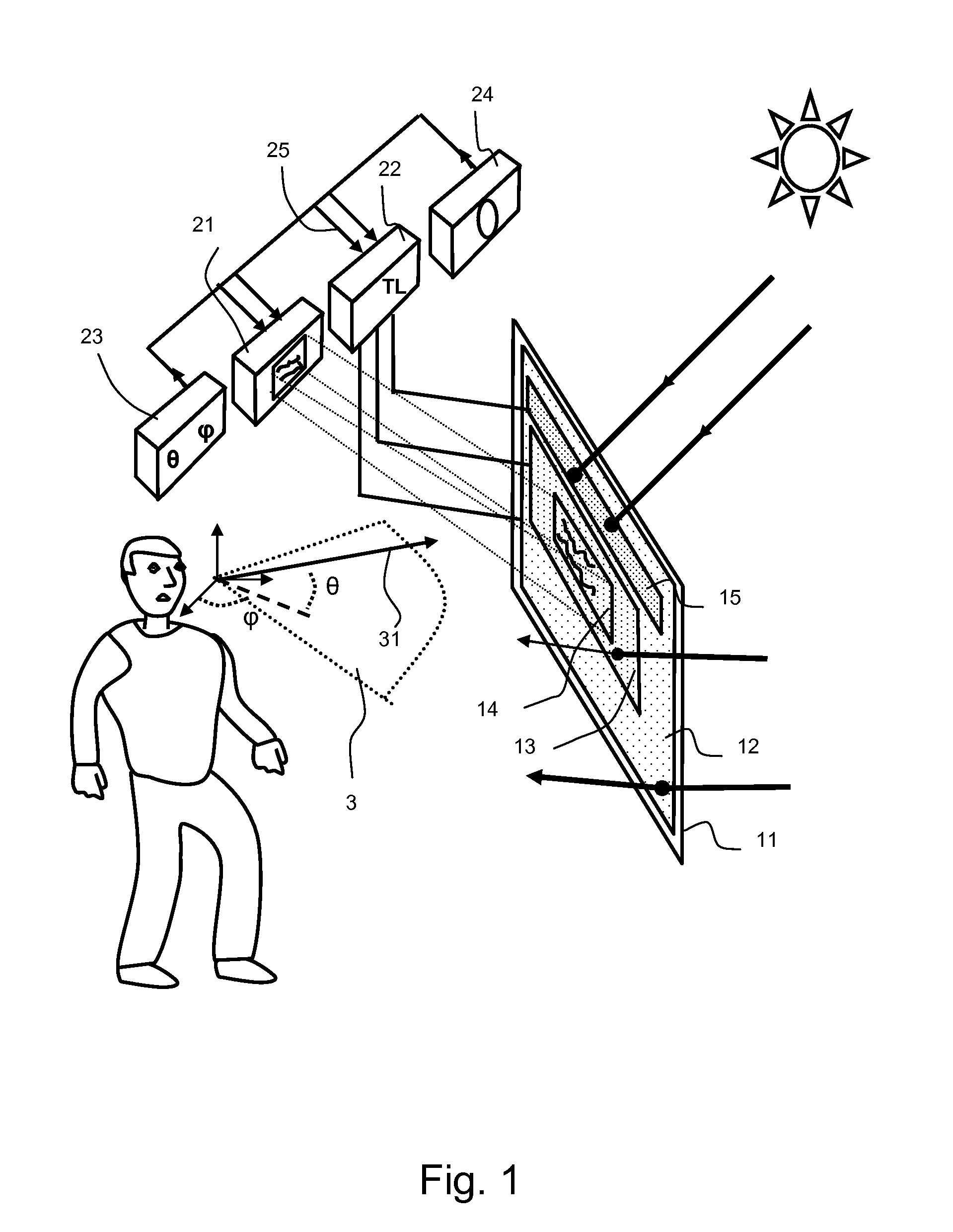
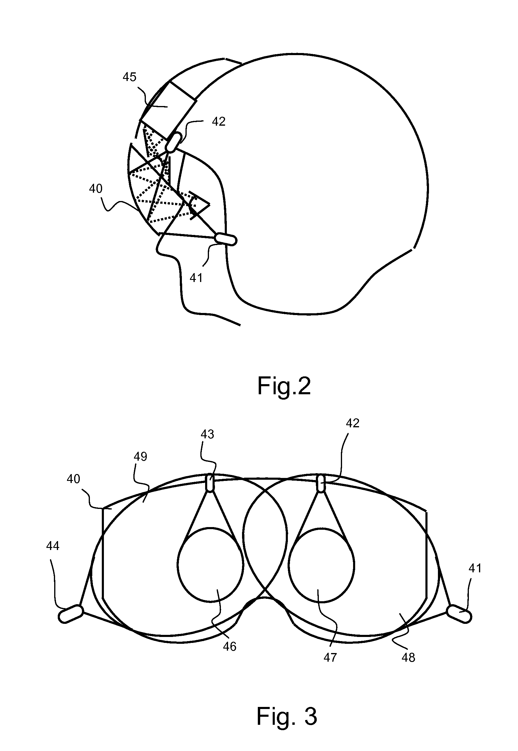
[0027]FIGS. 2 and 3 represent the vision equipment for a visual of an aircraft pilot helmet. According to this embodiment, the visor 40 of the helmet of the pilot is used as a zone for projecting images generated by a collimation image-projection device 45 positioned on the top front portion of the shell of the helmet. The visor 40 usually comprises, on the inner surface, the surface on the side of the wearer of the helmet, a semi-reflective layer making it possible to make visible to the wearer the images projected onto the visor. The layer of variable-light-transmission material is a material of the photochromic type and is deposited onto a surface of the visor totally or partially covering the surface of the visor. If the helmet comprises two visors, the layer of photochromic material can be deposited on either one of the two visors. In this case, the optical strip comprising the layer of photochromic material is distinct from the optical strip onto which the image is projected.

[...

second embodiment

[0035]FIG. 4 represents a second embodiment for an item of vision equipment for a helmet of an aircraft pilot. According to this embodiment, the visor 50 of the helmet of the pilot is used as a zone for the projection of images generated by a collimation image-projection device positioned on the upper front portion of the shell of the helmet. The visor 50 usually comprises on the inner surface, the surface on the side of the wearer of the helmet, a semi-reflective layer making it possible to make the images projected onto the visor visible to the wearer. The electrochromic material is deposited onto the surface of the visor behind the semi-reflective layer with respect to the user. An electrochromic material has properties making it possible to control its coefficient of light transmission by the application of an electric charge to the material.

[0036]The image-projection zones are defined by the field zones 52 centred on the visor and are covered with the electrochromic material. T...


PUM


Abstract

The invention relates to vision equipment including a translucent optical strip covering all or some of the visual field of the user of the said equipment and a device for projecting images onto the said strip in at least one zone of the visual field of the user, called the image-projection zone. The optical strip includes a plurality of zones covered by a layer of material with a controlled coefficient of light transmission, a zone at least covering the image-projection zone and in that the vision equipment also comprises a means for controlling the coefficient of light transmission capable of receiving status information and of controlling the coefficient of light transmission of each of the zones and independently of one another as a function of the said status information. The invention preferably applies to helmet visor equipment or head-up displays for an aircraft cockpit and to vision equipment in the motor vehicle field.

Description

CROSS-REFERENCE TO RELATED APPLICATION[0001]This application claims priority to foreign French patent application No. FR 0904769, filed on Oct. 6, 2009, the disclosure of which is incorporated by reference in its entirety.FIELD OF THE INVENTION[0002]The field of the invention relates to augmented reality vision equipment notably in the field of aviation for helmet visors.BACKGROUND OF THE INVENTION[0003]During a flight mission, an aircraft pilot has to monitor his flight environment while carrying out the tasks of piloting, navigation and completing his mission. The task of the pilot becomes particularly complex during flight phases at low altitude to monitor the obstacles and the terrain and, in the case of a tactical mission, to monitor moving objects. It is therefore normal to assist the pilot in the execution of his piloting functions with augmented reality systems. Specifically, there is, for example, vision equipment that, in real time, adds to the visual perception of the pil...

Claims


Application Information

Patent Timeline
IPC IPC(8): G02B27/01G02F1/03G01J1/42
CPCG02B27/01G02B2027/012G02B2027/0118G02B27/017
Inventor BAUDOU, JOELLALUQUE, LAURENTFRANCOIS, JEAN-MICHEL
Owner BEIJING VOYAGER TECH CO LTD
Why Eureka
Try Eureka