Electrical machine having a contact element for electrically connecting electrical components

a contact element and electrical connection technology, applied in the field of electric machines, can solve the problems of large wiring length, complex wiring geometry, complicated and expensive production, and high cost, and achieve the effect of rapid assembly of the rectifier modul

Active Publication Date: 2011-10-06
SEG AUTOMOTIVE GERMANY GMBH
View PDF19 Cites 4 Cited by
  • Summary
  • Abstract
  • Description
  • Claims
  • Application Information

AI Technical Summary

Benefits of technology

[0004]In accordance with the present invention, at least one of the electrical conductors is designed as an external connection conductor, which runs outside the substrate from one arc end area to the other arc end area. The result is thus a generally straight run of the external connection conductor from one of the arc end areas to the other arc end area. This produces a shortening of the wiring, which results in minor line losses. Furthermore, the manufacturing of the contact element is made simpler and more economical, since the substrate does not have to enclose the conductor and hence only a small amount of substrate is needed. At the same time, the geometry of the external connecting conductor may be greatly simplified compared to a conductor situated in the substrate, resulting in additional simplification of the manufacturing process. In addition, the risk of a short circuit between the external connecting conductor and other conductors situated in the substrate is minimized or completely eliminated. In order to prevent an electrical connection of the external conductor to other components in the electrical machine, it is preferably provided that the external connecting conductor is furnished with an insulating material so that the external connecting conductor is insulated toward the outside in the area between the arc end areas and is electrically contacted and / or contactable within the arc end areas.
[0005]A refinement of the present invention provides that the path of the external connecting conductor running between the arc end areas is arc-chord-shaped, arc-shaped and / or angular. The design of the path of the external connecting conductor between the arc end areas enables it to be adapted to the geometry of the electrical machine in the area in which the contact element is employed. The arc-chord-shaped path results in the external connecting conductor with the shortest wiring length, since the arc end areas are connected to one another in a direct route. The arc-shaped and angular paths, on the other hand, offer the option of adapting the external connecting conductor to the electrical machine. The path of the external connecting conductor in this case should be as short as possible and assume the simplest path possible, in order to be able to simplify a manufacturing process in this way.
[0006]A refinement of the present invention provides that when the external connecting conductor is arc-shaped, its arc runs opposite to the arc-shaped path of the contact element. This results in the contact element with its substrate and the external connecting conductor enclosing a particularly large opening, which is able to accommodate components of the electrical machine. Thus, a closed, ring-like structure is formed overall, which allows optimal placement of the contact element within the electrical machine.

Problems solved by technology

This results in a very complex wiring geometry, which is complicated and expensive to produce and requires great accuracy during installation in the substrate.
Furthermore, the angular path within the substrate due to the arc-shaped path of the contact element results in great wiring length, which leads to line losses.
This produces a shortening of the wiring, which results in minor line losses.
The design of the conductors as solid conductors results in the conductors being inherently stiff.
This results in a particularly rapid assembly of the rectifier module during the manufacturing process.

Method used


Image

  • Electrical machine having a contact element for electrically connecting electrical components
  • Electrical machine having a contact element for electrically connecting electrical components
  • Electrical machine having a contact element for electrically connecting electrical components

Examples


Embodiment Construction

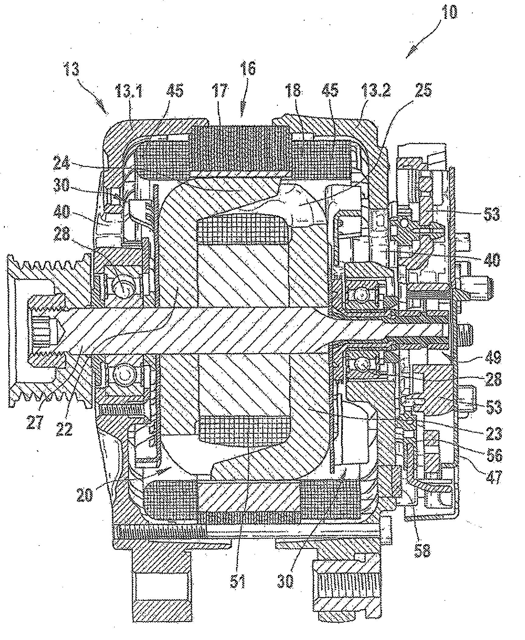
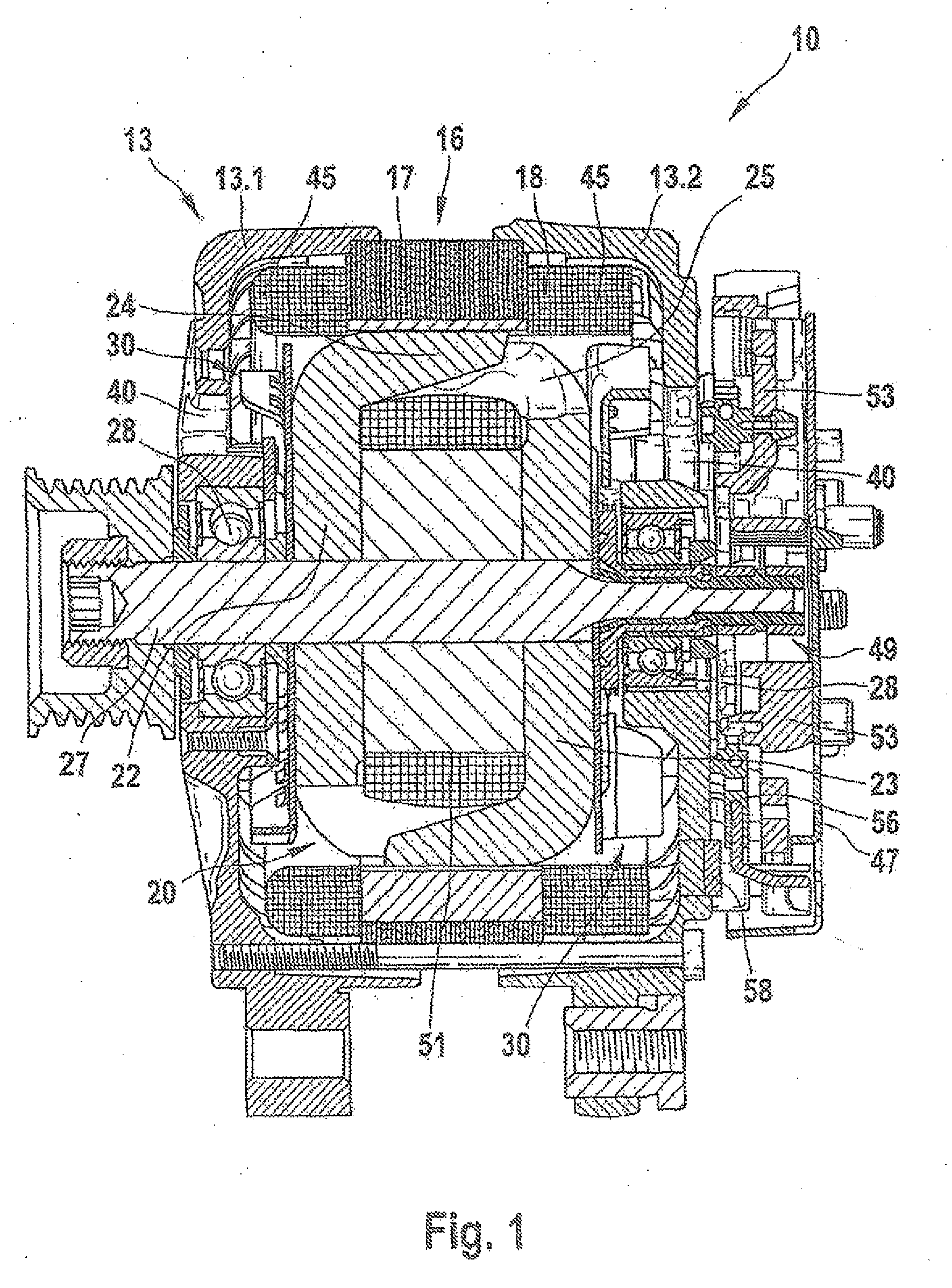
[0025]FIG. 1 shows a conventional electrical machine 10.

[0026]FIG. 1 shows a cross section through an electrical machine 10, implemented here as a generator or an alternator for motor vehicles. This electrical machine 10 has, among other things, a two-part housing 13, which is made up of a first end shield 13.1 and a second end shield 13.2. End shield 13.1 and end shield 13.2 accommodate a so-called stator 16, which has on the one hand a generally annular stator core 17, and into whose radially inward-facing, axially extending slots a stator winding 18 is inserted. The radially inward-facing slotted surface of this annular stator 16 surrounds a rotor 20, which is designed as a claw pole rotor. Rotor 20 is made up in part of two claw pole plates 22 and 23, at whose external circumferences claw pole fingers 24 and 25 are situated which extend in the axial direction. The two claw pole plates 22 and 23 are positioned in rotor 20 in such a way that their axially extending claw pole finge...


PUM


Abstract

An electrical machine, in particular a generator, preferably a claw pole generator, having a contact element for electrically connecting electrical components, which is made up of a generally arc-shaped, electrically non-conductive substrate having arc end areas, including electrical conductors for connecting the components. At least one of the electrical conductors is designed as an external connection conductor, which runs outside the substrate from one arc end area to the other arc end area.

Description

FIELD OF THE INVENTION[0001]The present invention relates to an electrical machine, in particular a generator, preferably a claw pole generator, having a contact element for electrically connecting electrical components, which is made up of a generally arc-shaped, electrically non-conductive substrate having arc end areas, including electrical conductors for connecting the components.BACKGROUND INFORMATION[0002]Conventionally, contact elements are employed in electrical machines for electrically connecting electrical components.[0003]European Patent No. EP 0 960 464 describes an electrical machine having a contact element which is of a generally arc-shaped design and has arc end areas. The contact element has a plurality of conductors that run within a substrate of the contact element. A conductor is provided in the contact element which extends from one arc end area to the other arc end area. The conductor extends through the substrate with an angular path. The angular path is need...

Claims


Application Information

Patent Timeline
Patent Type & Authority Applications(United States)
IPC IPC(8): H02K9/06H02K11/00
CPCH02K11/046H02K11/05
Inventor AMARAL, DANIEL
Owner SEG AUTOMOTIVE GERMANY GMBH
Why Eureka
Try Eureka