Projector

a projector and projector technology, applied in the field of projectors, can solve the problems of reducing the size and usability of the system, the inability of the minute mirror-based light modulator to rewrite image data, and the difficulty of matching the brightness, color tone and other characteristics of displayed images, and adjusting the projection position between the two projectors. , to achieve the effect of high-quality stereoscopic image and increased polarization of polarized light incident on the polar

Inactive Publication Date: 2011-10-06
COLUMBIA PEAK VENTURES LLC
View PDF2 Cites 22 Cited by
  • Summary
  • Abstract
  • Description
  • Claims
  • Application Information

AI Technical Summary

Benefits of technology

[0015]An advantage of some aspects of the invention is to provide a projector that displays a stereoscopic image by displaying images for left and right eyes having different polarization states alternately along the temporal axis, particularly, a projector that displays a stereoscopic image of high image quality even when the projector uses a light modulator that writes image data by using a line sequential or point sequential method.

Problems solved by technology

In the method using two projectors, it is difficult to match the brightness, color tone, and other characteristics of displayed images and adjust projection positions between the two projectors.
Further, using two projectors is problematic in terms of size reduction and usability of the system.
That is, the minute mirror-based light modulator cannot rewrite image data during each image display period.
However, since projection light having exited from the liquid crystal light modulator is divergent light, a segmented-area polarization switching device simply disposed immediately downstream of the liquid crystal light modulator disadvantageously receives the projection light whose diameter has increased after it had exited from each pixel in the liquid crystal light modulator.
In this case, however, the positions where image data are written in the liquid crystal light modulator still do not match the positions where the polarization states are switched in the segmented-area polarization switching device with precision of at least approximately one line (row) or several to several tens of lines in the pixel arrangement.
As a result, for example, part of an image for the left eye has a polarization state that should not present in the image for the left eye (but should present in an image for the right eye) or suffers from other unwanted phenomena.
The polarization state of a projected image is thus locally disturbed, and the local portion does not provide an appropriate stereoscopic viewing state, resulting in degradation in image quality.
The problem described above also occurs in a projector based on the point sequential method.
In this configuration, since groups of pixels which are arranged in the row direction and to which image data are written in the light modulator do not have a one-to-one relationship with the linear switching areas in the polarization switching device, the boundary position between portions where image data are written in the light modulator cannot be completely synchronized with the boundary position between portions where different polarization states are provided in the polarization switching device, resulting in slight local disturbance of the polarization state of a projected image.
The disturbance will, however, affect very little in practice when the size of the area where the disturbance of the polarization state occurs is much smaller than the entire image size.
For example, when a liquid crystal device is used as the light modulator, depending on the structure of the liquid crystal device and the physical properties and other factors of the liquid crystal material in the liquid crystal device, it takes a long time to rewrite image data or what is called a response time is long in some cases.

Method used


Image

  • Projector
  • Projector
  • Projector

Examples


first embodiment

[0046]A first embodiment of the invention will be described below with reference to FIGS. 1 to 7.

[0047]The present embodiment will be described with reference to what is called a three-panel liquid crystal projector in which three transmissive liquid crystal light valves are used as light modulators. The projector according to the present embodiment writes image data by using a line sequential method.

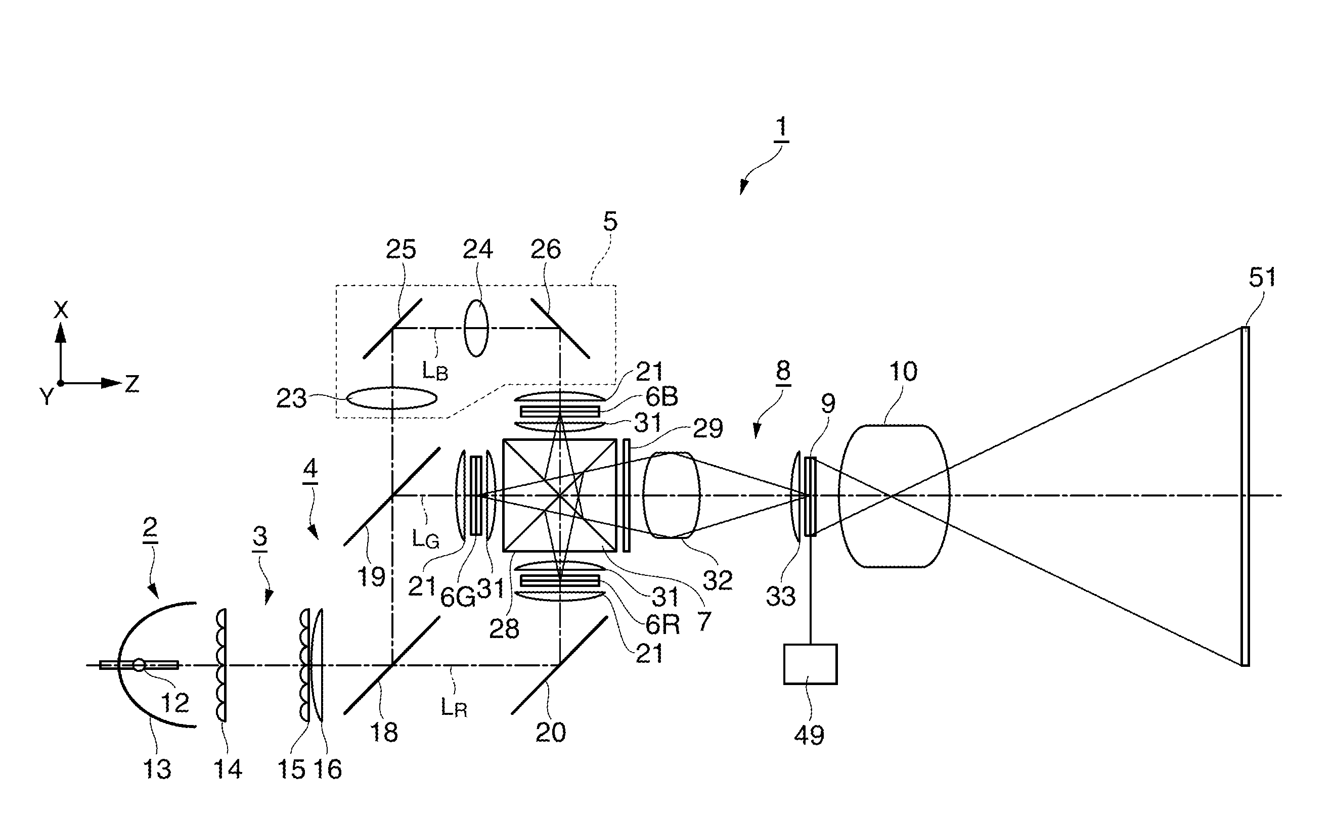
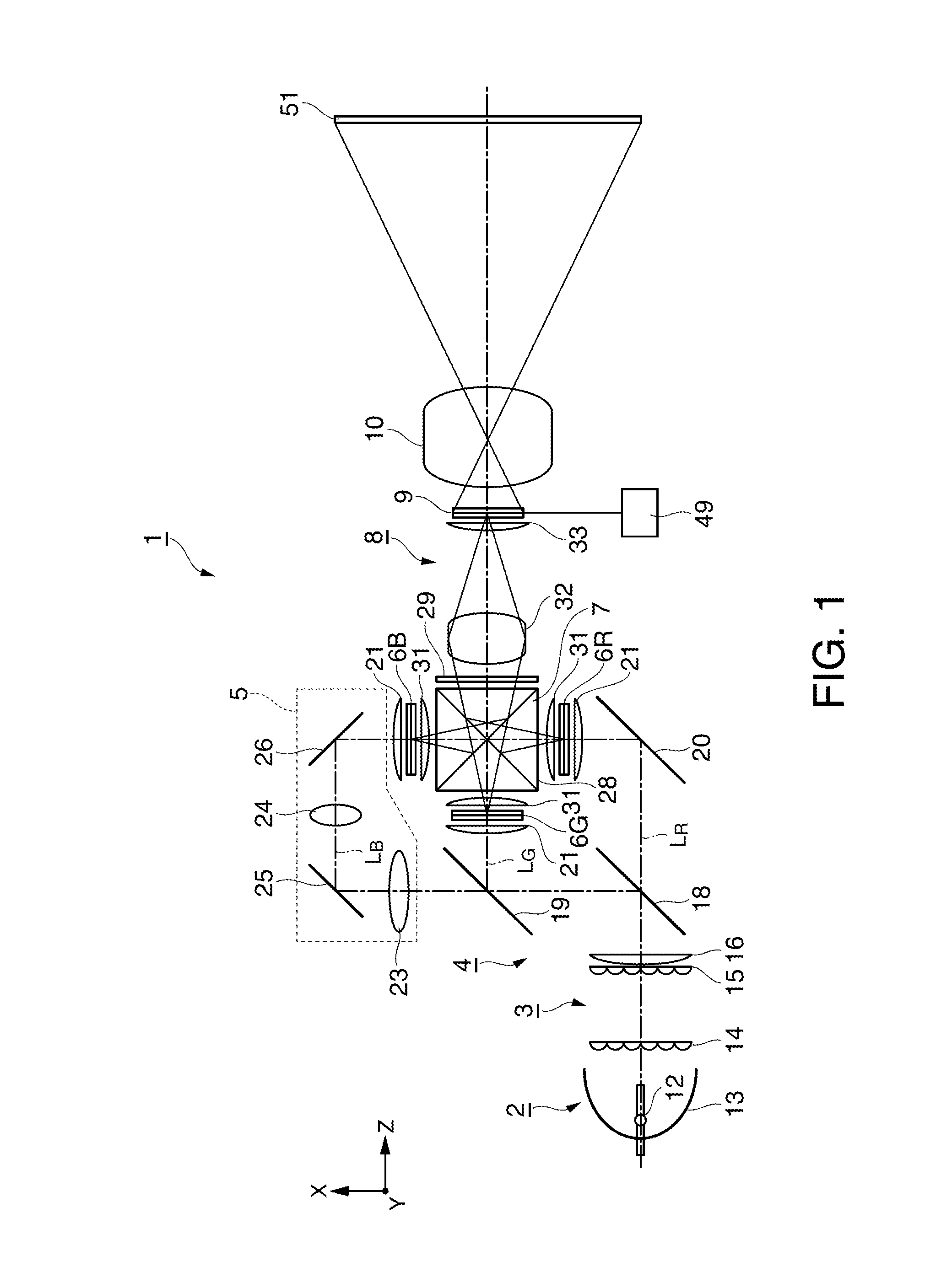
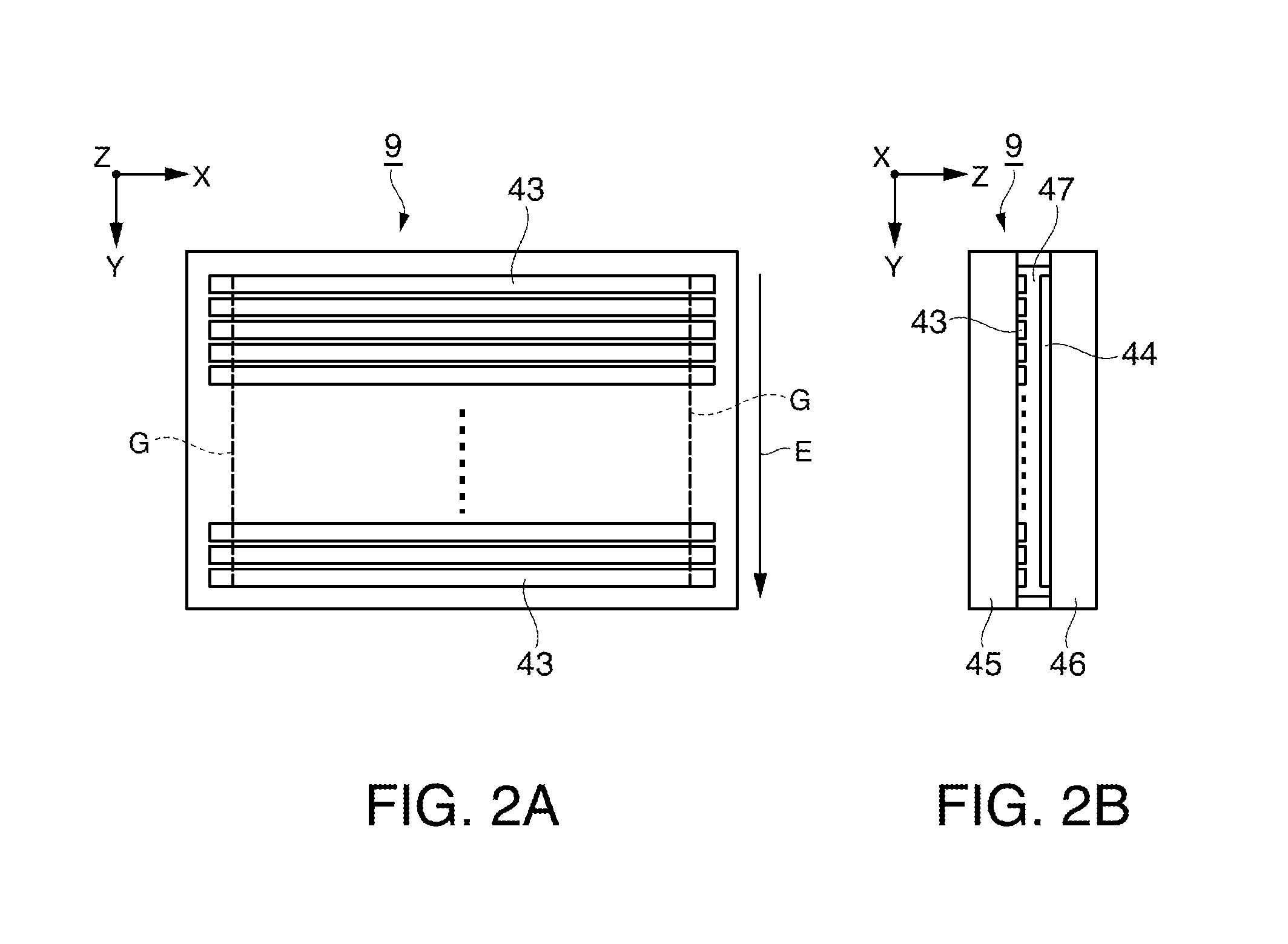
[0048]FIG. 1 shows a schematic configuration of the projector according to the present embodiment. FIGS. 2A and 2B show a segmented-area polarization switching device in the projector according to the present embodiment. FIG. 2A is a plan view of the device in an xy plane and viewed in a z-axis direction, and FIG. 2B is a cross-sectional view of the device taken along a yz plan and viewed in an x-axis direction. FIGS. 3A to 3C describe the relationship between the segmented-area polarization switching device and image light. FIGS. 4A to 4E show several examples of the configuration of a...

second embodiment

[0095]A second embodiment of the invention will be described below with reference to FIG. 8.

[0096]The basic configuration of a projector according to the present embodiment is the same as that in the first embodiment and only differs therefrom in terms of the way the liquid crystal light valves write image data. A description about this point will be only made.

[0097]FIG. 8 shows a polarization switching device in the projector according to the present embodiment. FIG. 8 is a plan view of the polarization switching device in the projector according to the present embodiment in an xy plane and viewed in the z-axis direction in FIG. 1.

[0098]The first embodiment has been described with reference to the case where the liquid crystal light valves 6R, 6G, and 6B write image data by using a line sequential method. Some liquid crystal light valves, however, write image data by using a point sequential method. The projector according to the present embodiment uses liquid crystal light valves ...

third embodiment

[0102]A third embodiment of the invention will be described below with reference to FIG. 9.

[0103]The first embodiment has been described with reference to the configuration in which transmissive liquid crystal light valves are used as the light modulators, whereas a projector according to the present embodiment will be described with reference to a configuration in which reflective liquid crystal light valves are used as the light modulators.

[0104]FIG. 9 shows a schematic configuration of the projector according to the present embodiment. In FIG. 9, the components common to those in the first embodiment shown in FIG. 1 have the same reference characters and no description of these components will be made.

[0105]In a projector 61 according to the present embodiment, dichroic mirrors 63 and 64, which form a color separation system 62, are provided on the light exiting side of the superimposing lens 16, which forms the optical integration system 3, as shown in FIG. 9. The dichroic mirro...


PUM


Abstract

A projector includes a liquid crystal light valve to which first image data and second image data are alternately written and a polarization switching device that has a plurality of switching areas and switches a polarization state between a first polarization state and a second polarization state for each of the switching areas. A boundary position between a switching area that provides the first polarization state and a switching area that provides the second polarization state moves in synchronization with a boundary position between an area where the first image data is written and an area where the second image data is written.

Description

[0001]The entire disclosure of Japanese Patent Application No. 2010-85850, filed Apr. 2, 2010 is expressly incorporated by reference herein.BACKGROUND[0002]1. Technical Field[0003]The present invention relates to a projector that projects and displays an optical image formed on a light modulator through a projection system on a screen, and more particularly to a projector that allows a viewer to observe a stereoscopic projected image through polarized eyeglasses.[0004]2. Related Art[0005]A technology for stereoscopically representing a displayed image by using a projector capable of large-screen display has been developed and brought into practical use. In stereoscopic image display using a projector, it is typical to use a parallax-based method in which images for the left and right eyes are projected on a screen and the left and right eyes view the respective images. In this process, the viewer needs to choose an image corresponding to each of the eyes. To this end, for example, a...

Claims


Application Information

Patent Timeline
Patent Type & Authority Applications(United States)
IPC IPC(8): G02B27/26G03B21/00G02B30/25H04N13/363
CPCG02B27/1026G02B27/1046G02B27/149G02B27/2264G02B27/26G03B35/26H04N13/0434H04N13/0459G03B21/2066G03B21/2073H04N9/3167H04N13/337H04N13/363G02B30/24G02B30/25
Inventor ITOH, YOSHITAKA
Owner COLUMBIA PEAK VENTURES LLC
Why Eureka
Try Eureka