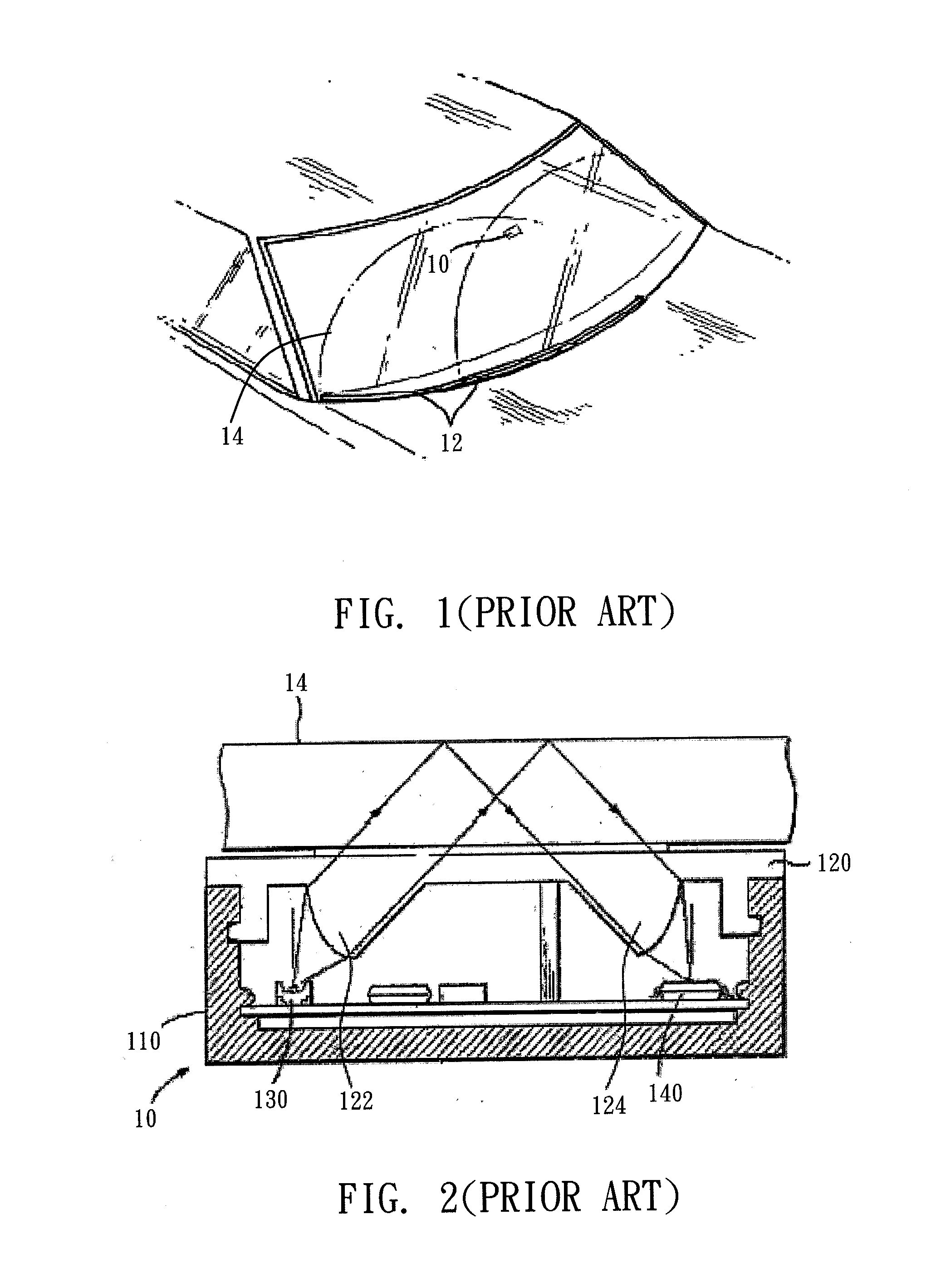
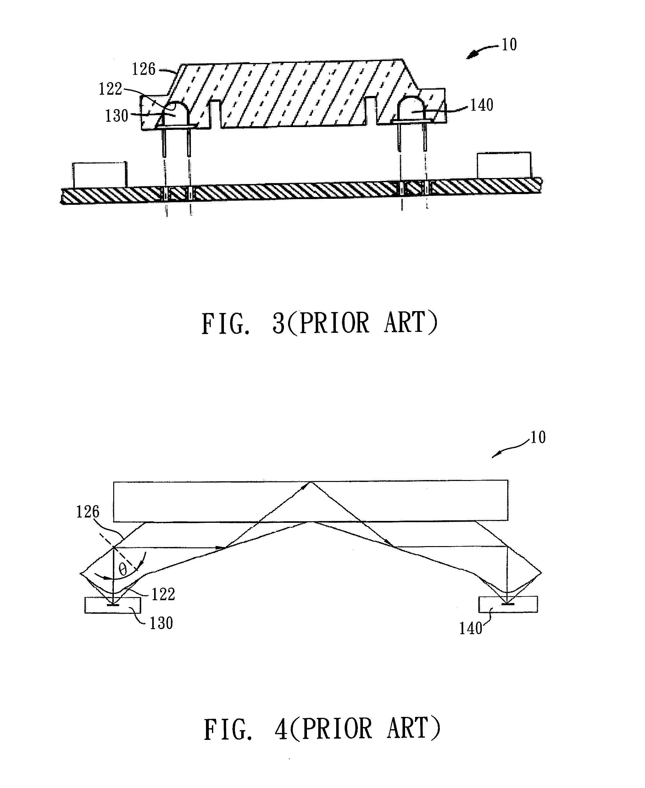
Rain sensor

a sensor and rain sensor technology, applied in the field of rain sensors, can solve the problems of low light efficiency, bad detection sensitivity, loss of part of light beams, etc., and achieve the effect of improving detection sensitivity of rain sensors, light efficiency, and increasing light efficiency

Inactive Publication Date: 2011-10-06
E PIN OPTICAL IND
View PDF8 Cites 16 Cited by
  • Summary
  • Abstract
  • Description
  • Claims
  • Application Information

AI Technical Summary

Benefits of technology

[0014]By using the technique of the present invention, the present invention can increase the light efficiency of the rain sensor up to 22%. The light efficiency increases about 54% by comparing with the conventional rain sensor, and the detection sensitivity of the rain sensor is effectively improved. Besides, the present invention eff...

Problems solved by technology

If the incident angle θ is small, some light beams will be refracted and some light beams will be reflected, hence a part of light beams are loss and the light beams finally received by the ...

Method used


Image

  • Rain sensor
  • Rain sensor
  • Rain sensor

Examples


Embodiment Construction

[0023]In order to make the present invention more explicit and detailed, the structures and the technique features of the present invention will be described below by taking best examples with the corresponding drawings below.

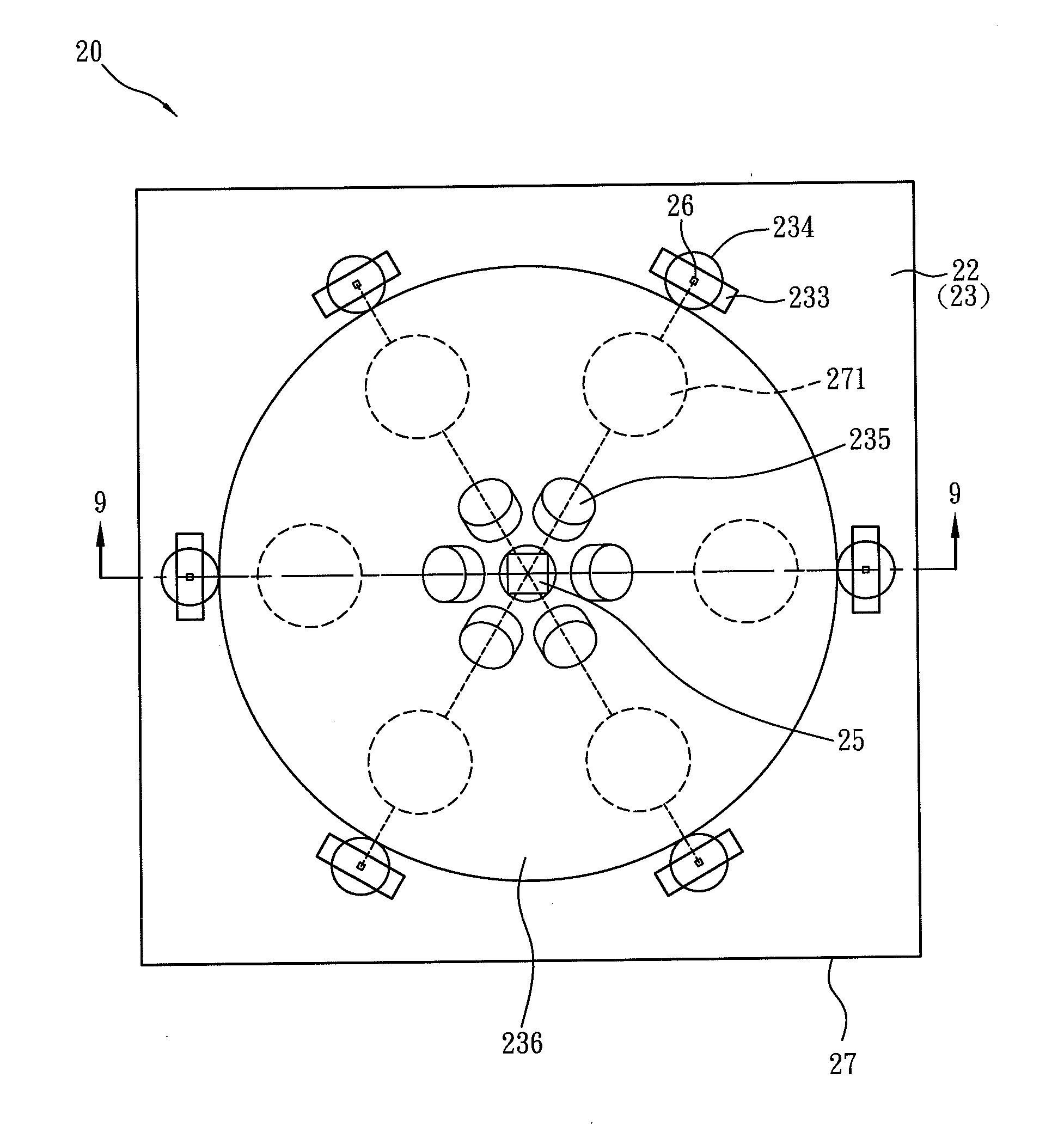
[0024]FIG. 5 is a solid diagram showing a structure of a rain sensor 20 according to one embodiment of the present invention. FIG. 6 is an exploded diagram of FIG. 5, wherein the covering surface 232 of the coupler 23 is facing downward. FIG. 7 is a solid diagram showing the covering surface 232 of the coupler 23 of the rain sensor 20. FIG. 8 is a top view showing the rain sensor 20 being used.

[0025]Referring to FIGS. 5 through 8, the rain sensor 20 of the present embodiment includes a housing 22 and a coupler 23. The housing 22 is made from opaque and plastic material, and is rectangle. The housing 22 has an opening 24. The coupler 23 is a transparent element that the light beams can pass, and the coupler 23 connects to the housing 22 and covers with the openi...


PUM


Abstract

A rain sensor mounted on a windshield of a vehicle comprises: a housing having an opening, at least an emitter disposed in the housing and used for emitting light beams, a coupler, and an optical detector. The coupler connecting and covering the opening of the housing, comprises: at least a collimator receiving and collimating the light beams into collimated light beams; and at least a groove having a deflection surface to reflect the collimated light beams that passes through the collimator and is incident to the deflection surface at an incident angle θ to the windshield. The optical detector disposed in the housing is used for receiving the collimated light beams reflected by the windshield and generating electrical signals. The present invention characterized in that the incident angle θ satisfies the following condition: 1.27<n*sin θ<1.52, wherein n is refractive index of the coupler.

Description

FIELD OF THE INVENTION[0001]The present invention relates to a rain sensor, and more particularly, to a rain sensor which detects rain or moisture on a windshield of a vehicle by optical reflecting.BACKGROUND OF THE INVENTION[0002]A wiper, a necessary equipment for a vehicle now, is used for removing rain or moisture accumulated on a windshield of a vehicle to enhance driver's vision through the windshield.[0003]The wiper now is generally operated by the driver through manually opening the wiper's switch, and it can intermittently swing to remove the rain. A wiper control system have recently been developed in recent years, which installs on the inner surface of the windshield, such as U.S. Pat. No. 5,898,183 and U.S. Pat. No. 5,661,303. They disclose a configuration of the wiper control system.[0004]Referring to FIG. 1, the wiper control system includes a rain sensor 10 attached to the inner surface of the windshield 14. If rain is accumulated on the outer surface of the windshield...

Claims


Application Information

Patent Timeline
IPC IPC(8): G01N21/55
CPCB60S1/0837G01N21/55B60S1/0888B60S1/0881
Inventor SHYU, SAN-WOEIKUO, MING-CHESHIH, BO-YUAN
Owner E PIN OPTICAL IND
Why Eureka
Try Eureka