
Image printing method with reduced banding

a banding artifact and image printing technology, applied in the field of electrotrophotographic printing, can solve the problems of consuming energy, adding cost and complexity to the printer, and unnecessary wear on the supply and toning members and the photoreceptor, so as to reduce banding artifacts, maintain image quality, and reduce banding. the effect of wear

Inactive Publication Date: 2011-10-06
EASTMAN KODAK CO
View PDF1 Cites 6 Cited by
  • Summary
  • Abstract
  • Description
  • Claims
  • Application Information

AI Technical Summary

Benefits of technology

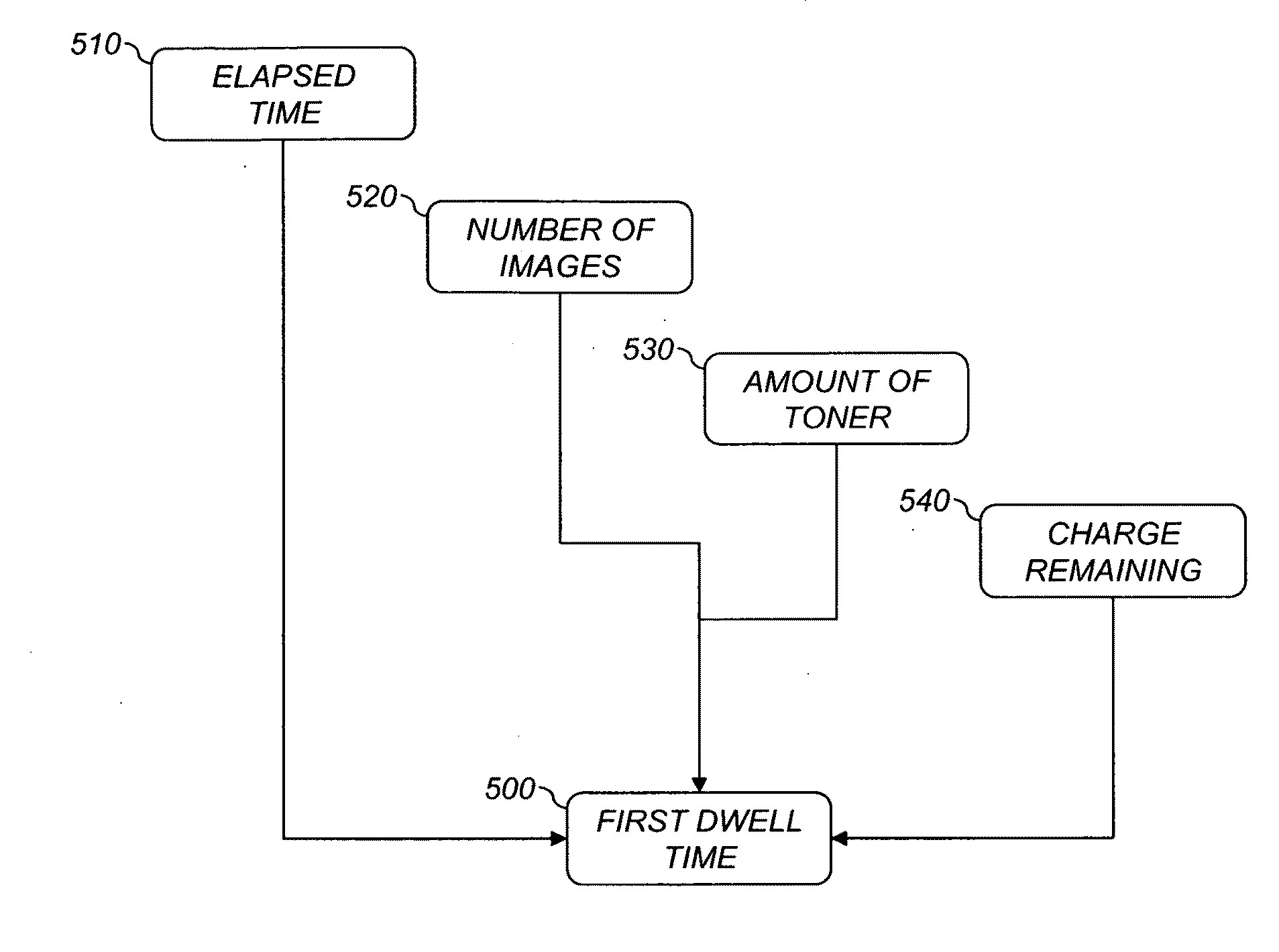
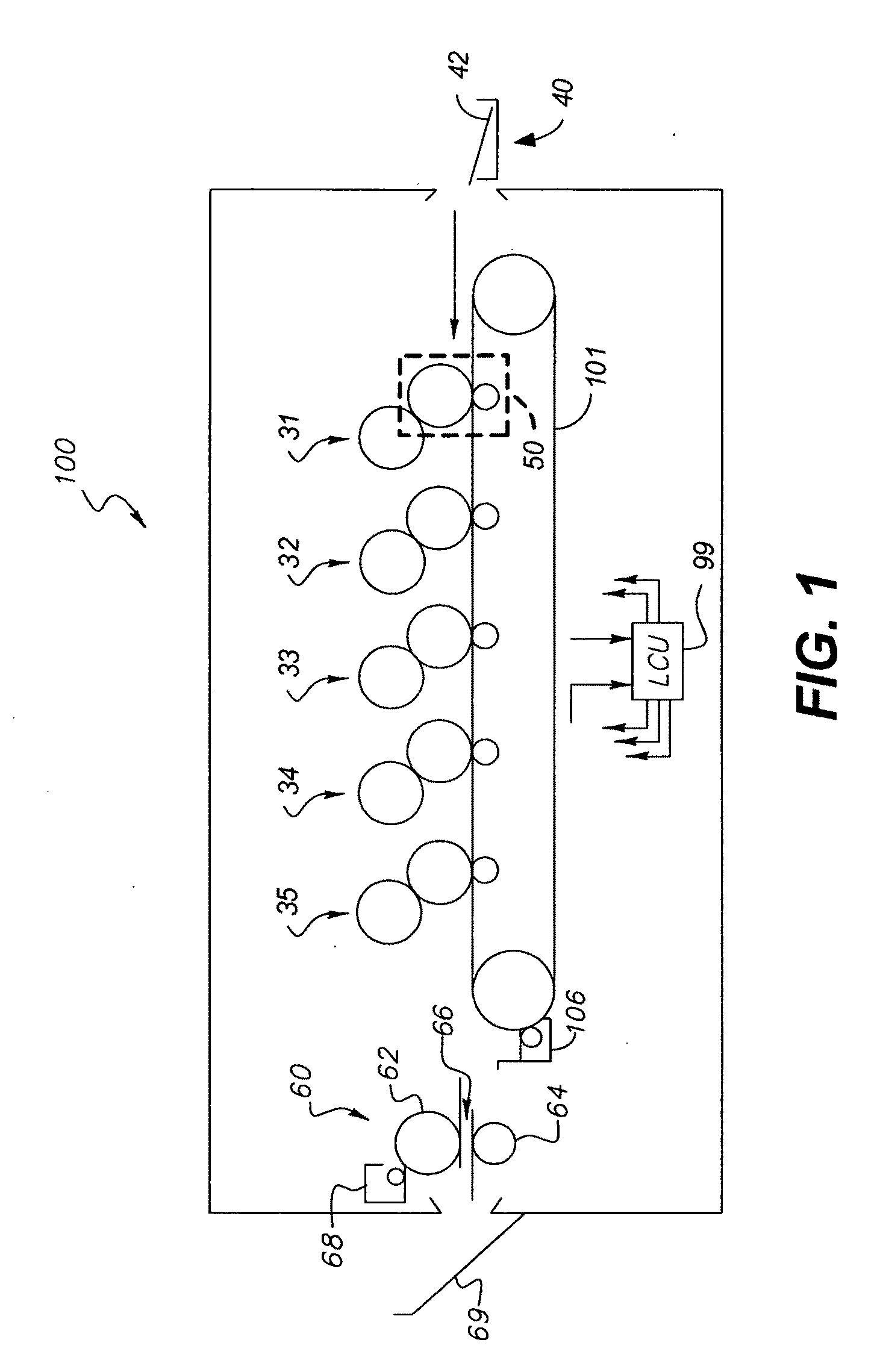
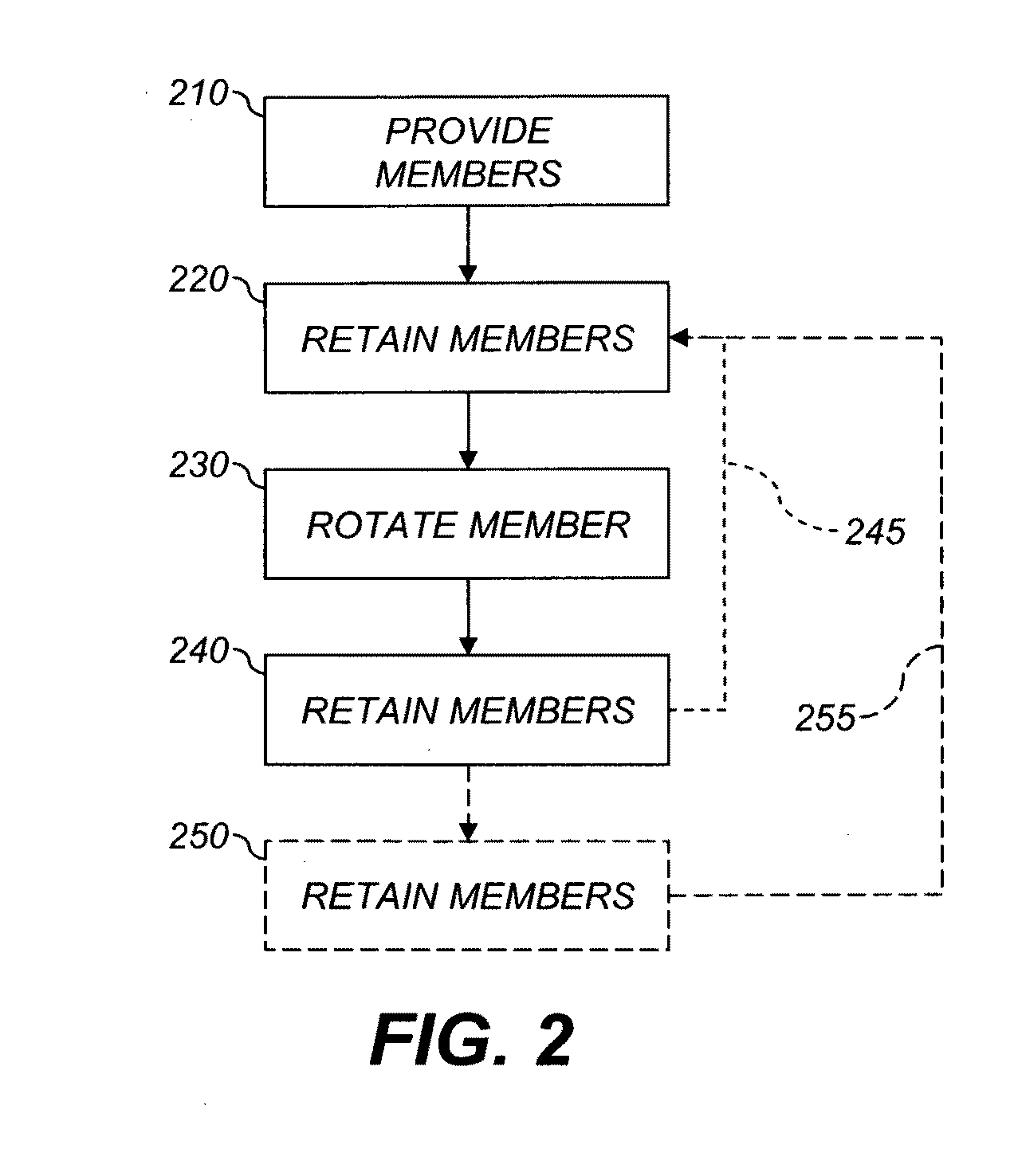
The present invention provides a method for reducing cross-track banding artifacts and wear in an electrophotographic print engine. The method involves rotating one of the members in the charge-transfer region to mitigate the banding artifacts, and then rotating both members in a second position to reduce wear on the print engine. This method does not require expensive hardware components and causes less toner stress than prior schemes. It is a low-cost solution for maintaining image quality.

Problems solved by technology

However, this adds cost and complexity to the printer.
However, over time, this causes unnecessary wear on the supply and toning members and the photoreceptor and consumes energy.
Moreover, this scheme causes increased levels of toner stress, which itself exacerbates the appearance of banding artifacts.
All of these factors reduce image quality.

Method used


Image

  • Image printing method with reduced banding
  • Image printing method with reduced banding
  • Image printing method with reduced banding

Examples


Embodiment Construction

[0029]As used herein, the terms “parallel” and “perpendicular” have a tolerance of ±10°.

[0030]In the following description, some embodiments of the present invention will be described in terms that would ordinarily be implemented as software programs. Those skilled in the art will readily recognize that the equivalent of such software can also be constructed in hardware. Because image manipulation algorithms and systems are well known, the present description will be directed in particular to algorithms and systems forming part of, or cooperating more directly with, the method in accordance with the present invention. Other aspects of such algorithms and systems, and hardware or software for producing and otherwise processing the image signals involved therewith, not specifically shown or described herein, are selected from such systems, algorithms, components, and elements known in the art. Given the system as described according to the invention in the following, software not spec...


PUM


Abstract

Cross-track banding artifacts and wear in an electrophotographic (EP) print engine are reduced. A development member and a supply member are disposed so that charge is transferred between them in a charge-transfer region. The members are retained in a first position with respect to each other for a first dwell time, and neither member is rotated during the first dwell time, so that charge is transferred between members in the charge-transfer region. One of the members is rotated so that at least one point on one of the members is moved out of the charge-transfer region. The members are retained in a second position with respect to each other for a second dwell time that is greater than the time for one revolution of the development member, wherein neither member is rotated during the second dwell time.

Description

FIELD OF THE INVENTION[0001]This invention pertains to the field of electrophotographic printing and more particularly to reducing nonuniformities in prints.BACKGROUND OF THE INVENTION[0002]Electrophotography is a useful process for printing images on a receiver (or “imaging substrate”), such as a piece or sheet of paper or another planar medium, glass, fabric, metal, or other objects as will be described below. In this process, an electrostatic latent image is formed on a photoreceptor by uniformly charging the photoreceptor and then discharging selected areas of the uniform charge to yield an electrostatic charge pattern corresponding to the desired image (a “latent image”).[0003]After the latent image is formed, toner particles are given a charge substantially opposite to the charge of the latent image, and brought into the vicinity of the photoreceptor so as to be attracted to the latent image to develop the latent image into a visible image. Note that the visible image may not ...

Claims


Application Information

Patent Timeline
Patent Type & Authority Applications(United States)
IPC IPC(8): G03G15/00
CPCG03G15/081
Inventor NO, YOUNG
Owner EASTMAN KODAK CO
Learn More