Stack type battery

a technology of stacking batteries and stacking plates, applied in the field of stacking batteries, can solve the problems of affecting the safety of users, and unable to serve the function of separating devices, and achieve the effect of high degree of safety

Inactive Publication Date: 2011-10-06
SANYO ELECTRIC CO LTD
View PDF3 Cites 38 Cited by
  • Summary
  • Abstract
  • Description
  • Claims
  • Application Information

AI Technical Summary

Benefits of technology

[0012]According to the present invention, it is possible to obtain a stack type battery that allows the separator to be thermally welded and fixed reliably without causing shrinkage or short circuiting and that can exhibit a shutdown function even at the time of abnormal heat generation so that it can offer a high degree of safety.

Problems solved by technology

This kind of separator has a problem that when heated to a high temperature of about 150° C. to 180° C. by, for example, abnormal heat generation, the separator melts or shrinks and can no longer serve the function as a separator.
When the thermal welding is carried out at such a high temperature, the portion of the separator surrounding the welded part also shrinks and causes dimensional variations, resulting in misalignment of the stacked layers.
In addition, the thermally fused portion of the separator may be chipped, which may become a cause of short circuits.
However, in this configuration, the low-melting point portion is contained only partially; therefore, it does not guarantee the shutdown function for stopping the charge-discharge reactions at the time of abnormal heat generation due to, for example, overcharging.

Method used


Image

  • Stack type battery
  • Stack type battery
  • Stack type battery

Examples


example 1

[0049]A stack type battery fabricated in the same manner as described in the foregoing embodiment was used as the stack type battery of this example.

[0050]The battery fabricated in this manner is hereinafter referred to as Battery A1 of the invention.

[0051]In the following examples and the drawings, parts and components that are or similar to those described in the foregoing embodiment and Example 1 above as well as in FIGS. 1 through 10 are denoted by like reference numerals and symbols, and no further details thereof are given unless necessary.

example 2

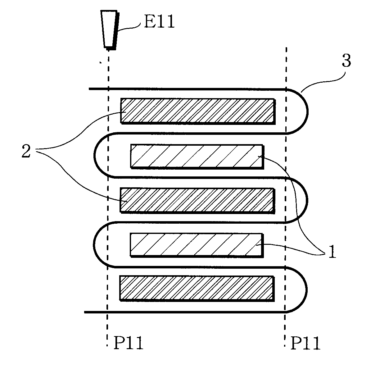
[0062]As illustrated in FIG. 11, the same separator 3 as used for the above-described Battery A1 of the invention was cut at a width of every 110 mm into 22 sheets of square-shaped separator portions 3a. In each one of the gaps between the positive and negative electrode plates 1 and 2 and on each one of the outermost faces, one sheet of the separator portion 3a was disposed so that a stack unit was constructed. Subsequently, as illustrated in the same figure, the metal terminal Ell heated at 200° C. was brought into contact with the separator portions 3a at weld positions P12 around the negative electrode plates 2 from the outermost face side, so that the separator portions 3a in the respective layers could be thermally welded and fixed together with the stacked positive and negative electrode plates 1 and 2. Thus, a stacked electrode assembly 100 shown in FIGS. 12 and FIG. 13 was obtained. A stack type battery was fabricated in the same manner as in the case of the foregoing Batte...

example 3

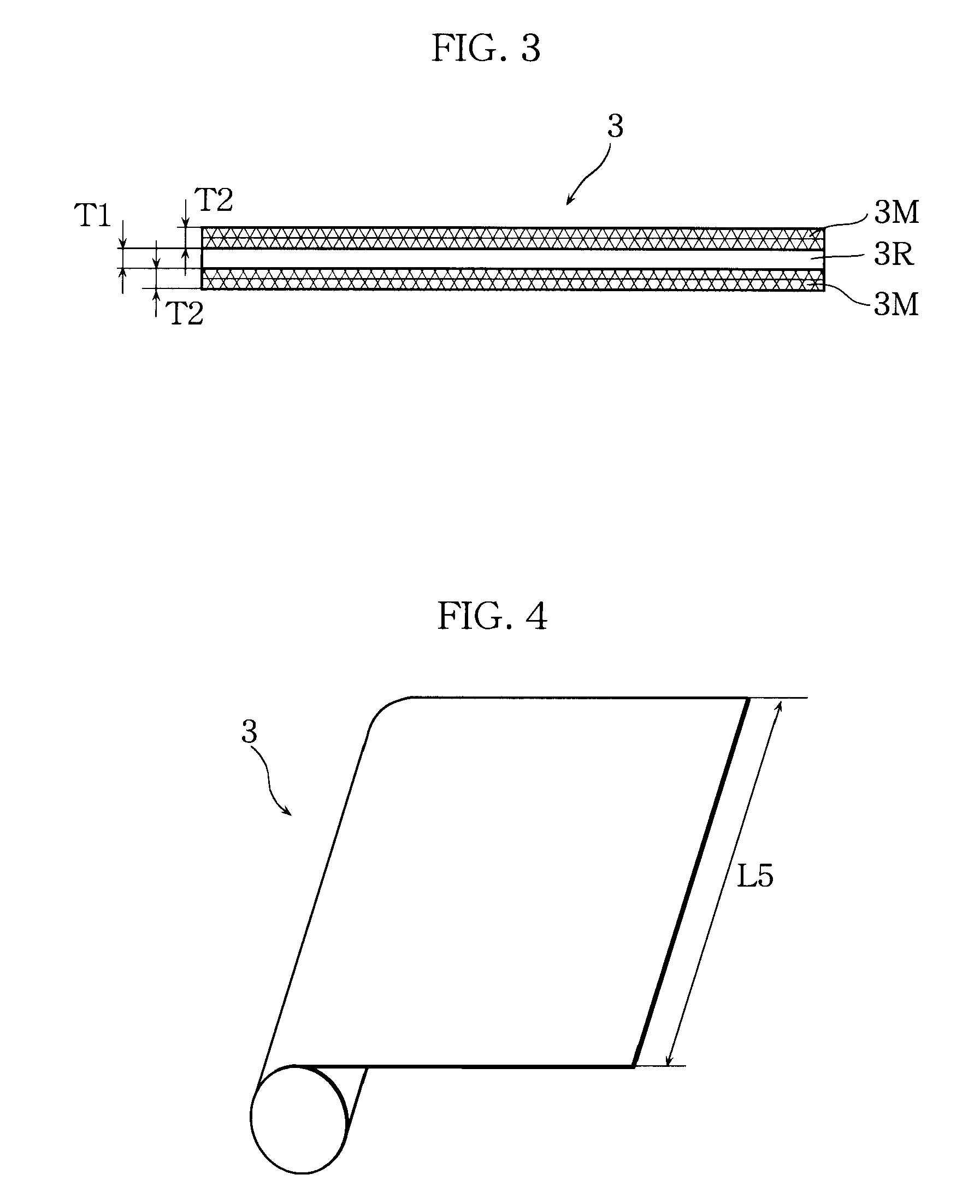
[0065]As illustrated in FIG. 14, a heat-melting layer 30M made of polyethylene (PE) and having a thickness T4=10 μm was formed over the entire surface of one side of a heat-resistant layer 30R made of an aramid resin and having a thickness T3=10 μm, to form a two-layer structure having a total thickness of T3+T4=20 μm. Thus, a separator 30 having a height of 110 mm was prepared. Next, the separator 30 was cut at a width of every 110 mm into 22 sheets of square-shaped separator portions 30a. Then, as illustrated in FIG. 15, in each one of the gaps between the positive and negative electrode plates 1 and 2 and on each one of the outermost faces, one sheet of the just-described separator portion 30a was disposed, whereby a stack unit was constructed. Subsequently, as illustrated in the same figure, the metal terminal E11 heated at 200° C. was brought into contact with the separator portions 30a at weld positions P13 around the negative electrode plates 2 from the outermost face side, t...


PUM

PropertyMeasurementUnit
temperatureaaaaaaaaaa

Abstract

A stack type battery has a plurality of positive electrode plates (1), a plurality of negative electrode plates (2), and a separator (3) interposed therebetween. The positive electrode plates (1) and the negative electrode plates (2) are alternately stacked one on the other. The separator (3) has a heat-resistant layer (3R) having heat resistance and heat-melting layers (3M), each of the heat-melting layers (3M) having a shutdown function and a melting point lower than the melting point of the heat-resistant layer (3R) and disposed over the entire surface of each of both sides of the heat-resistant layer (3R). The heat-melting layers (3M) of the separator (3) are fixed to each other by thermal welding.

Description

BACKGROUND OF THE INVENTION[0001]1. Field of the Invention[0002]The present invention relates to stack type batteries having high capacity and high-rate capability, which are used for, for example, robots, electric vehicles, and backup power sources. More particularly, the invention relates to a high-capacity lithium-ion battery that uses a separator having a multi-layered structure composed of a heat-resistant layer and a heat-melting layer to offer a high degree of safety.[0003]2. Description of Related Art[0004]In a stack type battery, positive electrode plates are sandwiched by a separator and the peripheral portions of the separator are thermally welded to each other so that the positive electrode plates are secured in a stacked condition. In this structure, a microporous film made of a polyolefin resin has been commonly used conventionally. This kind of separator has a problem that when heated to a high temperature of about 150° C. to 180° C. by, for example, abnormal heat gen...

Claims


Application Information

Patent Timeline
Patent Type & Authority Applications(United States)
IPC IPC(8): H01M2/16H01M2/18H01M50/451H01M50/457H01M50/466
CPCH01M2/16H01M2/1686H01M2/18H01M4/485Y02T10/7011H01M10/0525H01M10/0568H01M10/0569H01M4/587Y02E60/10H01M50/457H01M50/466H01M50/451
Inventor SHINYASHIKI, YOSHITAKAMAEDA, HITOSHIFUNAHASHI, ATSUHIROFUJIWARA, MASAYUKITANI, YUJI
Owner SANYO ELECTRIC CO LTD
Why Eureka
Try Eureka