Canister with heater

a heater and canister technology, applied in the field of canisters, can solve the problems of insignificant desorption efficiency of active carbon in the canister by the heated air, air polluted and wasted, etc., and achieve the effect of improving the desorption efficiency of active carbon

Inactive Publication Date: 2011-10-13
KOREA FUEL TECH
View PDF7 Cites 19 Cited by
  • Summary
  • Abstract
  • Description
  • Claims
  • Application Information

AI Technical Summary

Benefits of technology

[0028]The present invention has been made in an effort to solve the above-described problems associated with prior art, and an object of the present invention is to provide a canister with a heater which can supply heat, required for desorption of fuel gas adsorbed onto active carbon filled in the canister, to the entire active carbon, thus improving the desorption efficiency of the active carbon.

Problems solved by technology

The fuel gas contains harmful components such as hydrocarbon (HO) and the like, and thus, if the fuel gas is discharged to the outside of the vehicle, the air is polluted and the fuel is wasted.
However, the above-described canister has a problem in that the temperature of the air heated by the heater is not greater than 100° C. and the actual temperature of the air supplied to the active carbon is maintained at about 80° C.
Moreover, the heat of the air heated and supplied to the active carbon is absorbed by the active carbon around an inlet port thereof such that the heat is not uniformly distributed to the entire active carbon.
As a result, the desorption efficiency of the canister by the heated air is insignificant, which just meets the partial zero emission vehicle (PZEV) standards for exhaust emissions.
However, since the heat is supplied only to the active carbon being in contact with the outlet pipe, the heat is absorbed by the corresponding active carbon, and thereby the heat is not supplied to the entire active carbon.
As a result, the desorption efficiency of the canister is insignificant, which just meets the partial zero emission vehicle (PZEV) standards for exhaust emissions.
However, the temperature of the heat generated by the heat storage material filled in the chamber during desorption reaction is lower than a predetermined temperature, and thus the canister does not satisfy the desorption rate required by the hybrid vehicle.

Method used


Image

  • Canister with heater
  • Canister with heater
  • Canister with heater

Examples


Embodiment Construction

[0043]Hereinafter, preferred embodiments in accordance with the present invention will be described with reference to the accompanying drawings. The preferred embodiments are provided so that those skilled in the art can sufficiently understand the present invention, but can be modified in various forms and the scope of the present invention is not limited to the preferred embodiments.

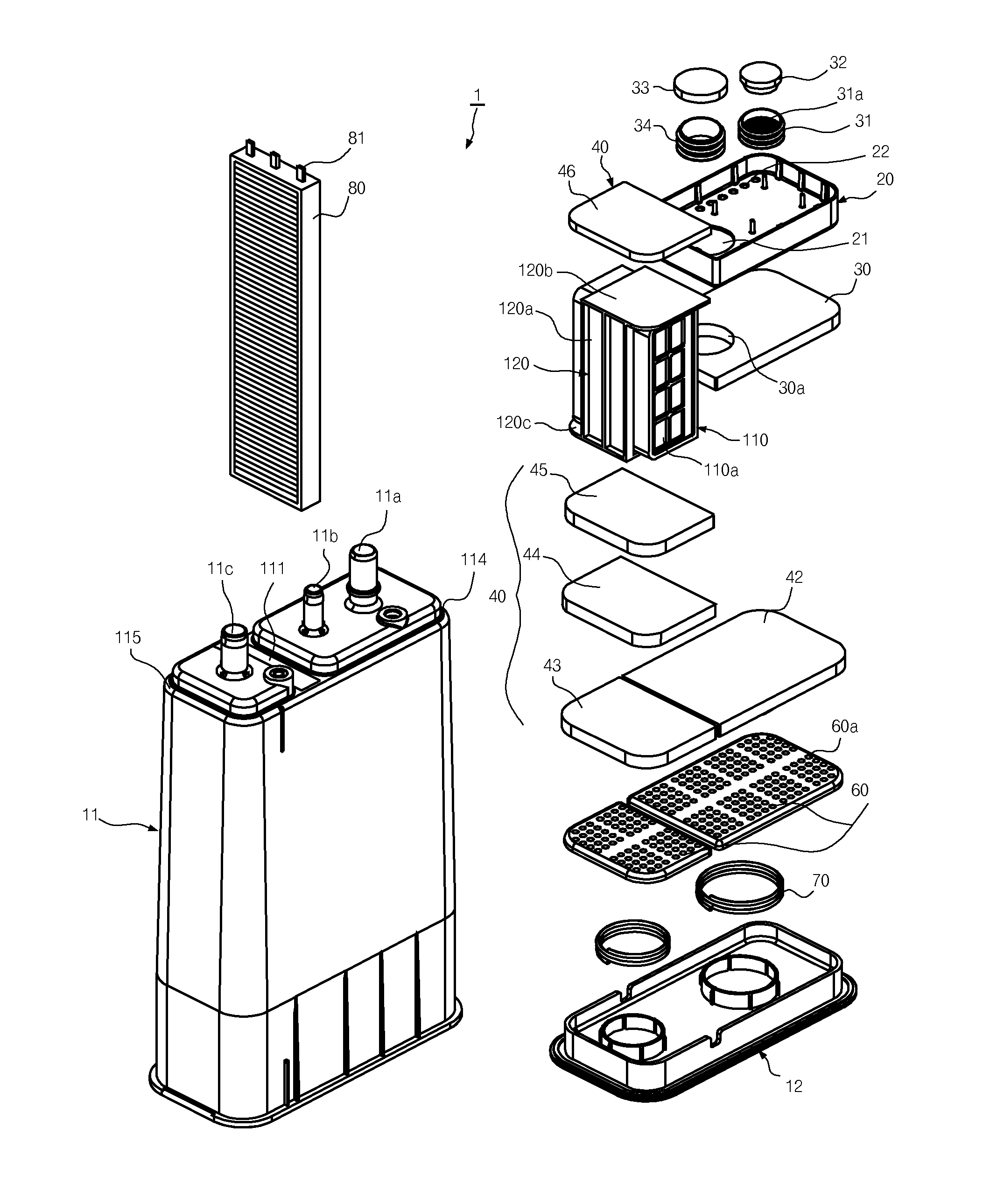
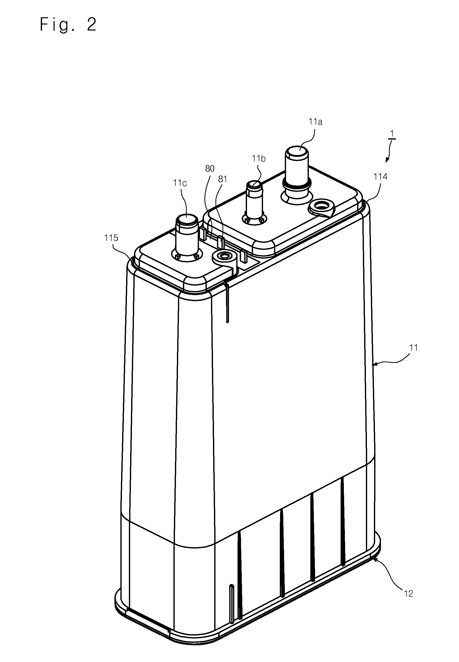
[0044]FIG. 2 is a perspective view of a canister with a heater according to a preferred embodiment of the present invention, FIG. 3 is an exploded perspective view of the canister of FIG. 2, and FIG. 4 is a front cross-sectional view of the canister of FIG. 2.

[0045]The canister 1 includes a canister housing 11 and a lower plate 12 connected to the bottom of the canister housing 11. A fuel gas reducing device 10, a diffusion trap 20, a coating filter 30, a support filter 40, active carbon 50, a strainer 60, and an elastic member 70 are provided in the canister housing 11.

[0046]A pocket 111 is provided i...


PUM


Abstract

Disclosed herein is a canister mounted in a vehicle to reduce the discharge of fuel gas. The canister of the present invention includes at least one pocket installed in a canister housing. The pocket divides the inner space of the canister housing into first and second spaces. A heater is inserted into the pocket from the outside of the canister housing. The heater generates heat during running of an engine to heat active carbon filled in the canister. When the active carbon is heated, fuel gas adsorbed onto the active carbon in a liquid phase is easily evaporated and supplied to the engine. The heater can significantly improve desorption efficiency of the fuel gas by the active carbon.

Description

CROSS-REFERENCE TO RELATED APPLICATION[0001]This application claims the benefit of Korean Patent Application No. 10-2009-0091104, filed on Sep. 25, 2009, the entire disclosure of which is hereby incorporated by reference.BACKGOUND OF THE INVENTION[0002]1. Field of the Invention[0003]The present invention relates to a canister mounted in a vehicle to reduce the discharge of fuel gas and, more particularly, to a canister with a heater configured such that fuel gas adsorbed onto active carbon filled in the canister is more easily desorbed from the active carbon and introduced into an engine.[0004]2. Description of Related Art[0005]Typically, an apparatus for storing fuel gas generated from a fuel tank and transferring it to an engine is employed in a vehicle, and such an apparatus is generally referred to a canister.[0006]Fuel required for driving the engine is stored in the fuel tank. When the fuel is evaporated in the fuel tank by environmental factors such as ambient temperature and...

Claims


Application Information

Patent Timeline
Patent Type & Authority Applications(United States)
IPC IPC(8): F02M33/06
CPCB60K15/03504F02M25/0854B60K2015/03514F02M31/125
Inventor KIM, HYUN KIHWANG, TAE KYUCHOI, JOON YOUNGKIM, YU MIN
Owner KOREA FUEL TECH
Why Eureka
Try Eureka