
Apparatus for transferring energy to an accumulator and system for charging an electric accumulator

Active Publication Date: 2011-10-13
NXP BV
View PDF21 Cites 52 Cited by
  • Summary
  • Abstract
  • Description
  • Claims
  • Application Information

AI Technical Summary

Benefits of technology

[0018]According to an embodiment the core comprises a material having a relative magnetic permeability greater than 30, in particular greater than 40. The permeability is a measure of the ability of a material to confine the formation of a magnetic field within itself. In other words, it is the degree of magnetization that a material obtains in response to an applied magnetic field. Permeability is the inductance per unit length and may be measured in Henry per meter (H / m). The relative permeability of a material is the ratio of the permeability of the material to the permeability of free space which is given by the magnetic constant μ0. Thus, the permeability of the material comprised in the core is 30 times, in particular 40 times, greater than the permeability of free space. Thereby, the magnetization of the core in response to an applied magnetic field is 30 times, in particular 40 times, greater than the magnetization that the free space obtains in response to the applied magnetic field. Thereby, the magnetic field may be enhanced within the core according to an embodiment compared to a core having a smaller relative magnetic permeability. The magnetic field may have a greater magnitude within the core compared to a coil having a “core” not comprising a solid material, in particular comprising only air. Thereby, the efficiency of transfer of the received energy may be improved.
[0055]According to an embodiment the charging station comprises an oscillator for generating an electric signal having a frequency between 4 MHz and 20 MHz, in particular between 8 MHz and 16 MHz, the electric signal being deliverable to the further wire. Thereby, the charging station may generate an alternating or oscillating magnetic field having a predetermined frequency. In particular, the tuning controller of the apparatus for transferring energy to the accumulator may tune its resonance frequency to essentially match the frequency of the electric signal generated by the oscillator of the charging station to thereby improve the efficiency of transfer of energy from the charging station to the apparatus for transferring energy to the accumulator, in particular to the hearing instrument comprising the accumulator.

Problems solved by technology

In particular, for elder people replacement of the often tiny batteries is difficult, since the elder people often are not very skilled to handle tiny batteries.
Further, the battery door occupies space in the hearing aid which may limit miniaturization and may limit also battery capacity.
Alternatively, when the hearing aid is equipped with a rechargeable battery or accumulator, the accumulator is typically taken out of the hearing aid presenting essentially similar problems as known rechargeable batteries.
The solutions known from the prior art for transferring energy to a hearing aid or generally for transferring energy to an accumulator are often not easily integrated in miniaturized hearing instruments and often do not have capabilities for effectively charging the accumulator.

Method used


Image

  • Apparatus for transferring energy to an accumulator and system for charging an electric accumulator
  • Apparatus for transferring energy to an accumulator and system for charging an electric accumulator
  • Apparatus for transferring energy to an accumulator and system for charging an electric accumulator

Examples


Embodiment Construction

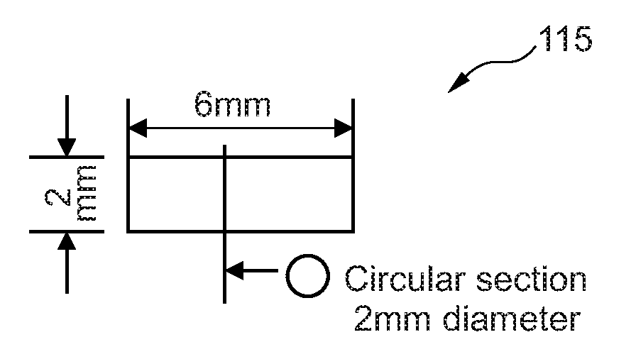
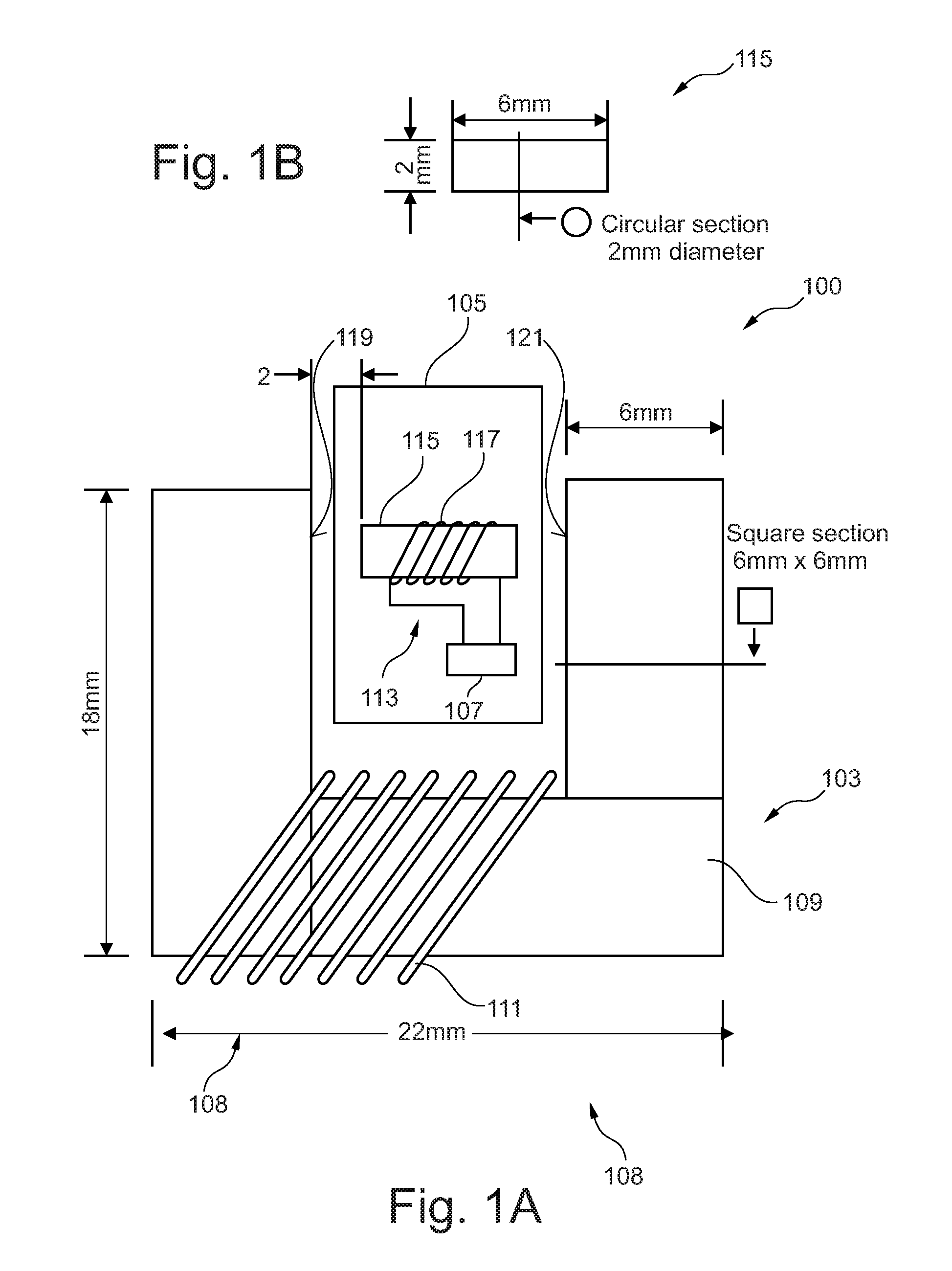
[0067]FIG. 1 schematically shows a system 100 for charging an electric accumulator according to an embodiment. The system 100 comprises a further coil 103 (primary coil) of a charging station and a hearing instrument 105 having an accumulator 107 to be charged (between the coil 113 and the accumulator 107 at least one not illustrated rectifier is connected).

[0068]The hearing instrument further comprises a casing harbouring the accumulator 107 and a microphone for converting an acoustic signal into an electric signal, an amplifier for amplifying the electric signal and a loudspeaker for generating an acoustic signal from the amplified electric signal, wherein the acoustic signal represents an amplified acoustic signal to be supplied to an ear of a person having reduced hearing capabilities. The further coil 103 comprises a further core 109 which has a U-shape. In particular, the further core 109 comprises a horizontal section having a length of 22 mm and two vertical sections 108 hav...


PUM


Abstract

It is provided an apparatus for transferring energy to an accumulator, the apparatus having a core and a wire wound around the core thereby forming a coil, wherein the coil is adapted to receive energy from a magnetic field, wherein the wire is connectable to the accumulator to transfer the received energy to the accumulator. A charging station for generating a magnetic field for transferring energy to an accumulator is provided, and a system for charging an electric accumulator is provided, wherein the system includes an apparatus as described above; and a charging station having a further wire wound such as to form a further coil.

Description

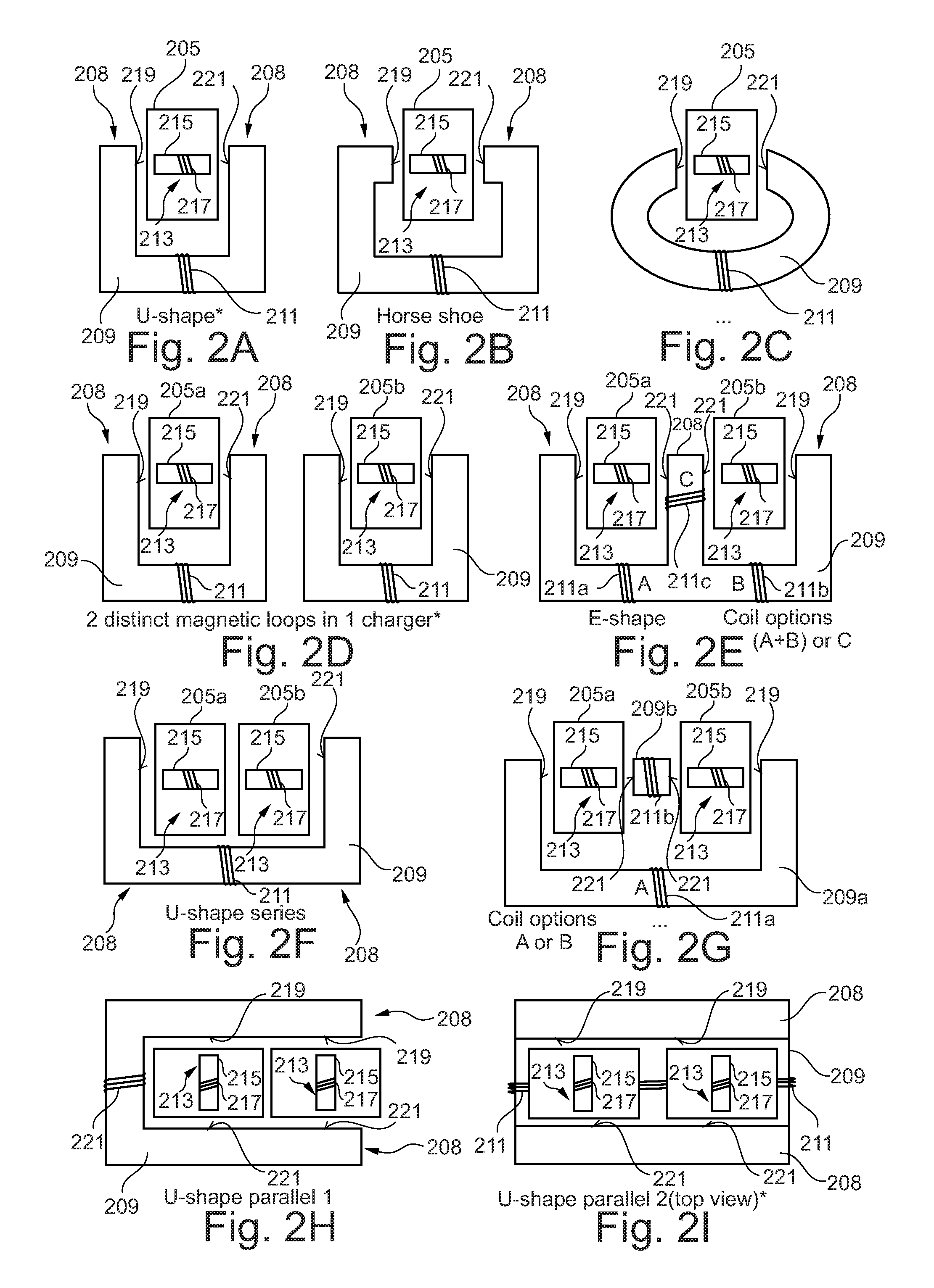
FIELD OF THE INVENTION[0001]The present invention relates to an apparatus for transferring energy to an electric accumulator, to a system for charging an electric accumulator and to a method for transferring energy to an accumulator. In particular, the present invention relates to an apparatus for transferring energy to an accumulator comprised in a hearing instrument. Further in particular, the present invention relates to a system for charging an electric accumulator comprised in a hearing instrument.[0002]Proposed is an inductive coupling system for wireless (contactless) charging of a rechargeable hearing instrument, comprising a charger having a primary coil characterized by a U-shaped primary ferrite core, and a hearing instrument device having a secondary coil with a ferrite rod core.[0003]Said secondary coil may be connected to a battery charging subsystem as well as to a short-range communications subsystem.BACKGROUND OF THE INVENTION[0004]A hearing instrument or hearing ai...

Claims


Application Information

Patent Timeline
IPC IPC(8): H02J7/00
CPCH02J7/025H02J7/0044H02J50/12H02J50/70
Inventor AERTS, STEVENTHOEN, STEVEN MARKDAENEN, STEVEN
Owner NXP BV
Learn More