Image displaying method for a head-mounted type display unit

a display unit and display method technology, applied in the field of image displaying methods of head-mounted type display units, can solve the problems of imbalance between subtitles, subtitle display sections are disabled, and subtitles cannot be displayed by the subtitle display section

Active Publication Date: 2011-10-13
SONY CORP
View PDF2 Cites 56 Cited by
  • Summary
  • Abstract
  • Description
  • Claims
  • Application Information

AI Technical Summary

Benefits of technology

[0064]In the image displaying method according to the first embodiment of the present invention, a designation identification code and display time information are sent at the predetermined intervals of time from the outside to the control means. The control means reads out the data whose data identification code coincides with the received designation identification code from the storage means and controls the image forming apparatus to display an image based on the read out data for a period of time corresponding to the received display time information. Accordingly, even if the control means fails in reception of a designation identification code and / or display time information sent thereto from the outside, it can try to receive the designation identification code and the display time information again or repeatedly. Therefore, the designation identification code and the display time information can be received with certainty. As a result, for example, even in the case where a designation identification code and display time information are to be received by a plurality of head-mounted type display unit, the plural head-mounted type display units can display the same image at the same time with certainty. Consequently, occurrence of a problem that an image cannot be displayed on a head-mounted type display unit can be prevented with certainty.
[0065]In the image displaying method according to the second embodiment of the present invention, the control means reads out one of the plural different size display data of the data whose data identification code coincides with the received designation identification code in response to the distance between the observation object and the head-mounted type display unit from the storage means, and controls the image forming apparatus to display an image based on the one different size display data. Therefore, imbalance between the visually observed size of the observation object and the size of the image is less likely to occur.
[0066]In the image displaying method according to the third embodiment of the present invention, the control means reads out one of the plural different language display data of the data whose data identification code coincides with the received designation identification code from the storage means, and controls the image forming apparatus to display an image based on the one different language display data. Therefore, display of an image based on a language used by an observer or spectator can be carried out readily.

Problems solved by technology

If such a problem occurs particularly in the case where subtitle information transmitted from a single signal transmission section is received by a plurality of signal reception sections, then the plural subtitle display sections are disabled from simultaneously displaying the subtitles, and in the first place, the subtitles cannot be displayed by the subtitle display section.
Furthermore, depending upon the position of the seat on which the spectator is seated, some imbalance sometimes occurs between the size in which a character in a theatrical performance or the like who is an object of appreciation in watching of the theatrical performance and the size of characters of the subtitles.

Method used


Image

  • Image displaying method for a head-mounted type display unit
  • Image displaying method for a head-mounted type display unit
  • Image displaying method for a head-mounted type display unit

Examples


working example 1

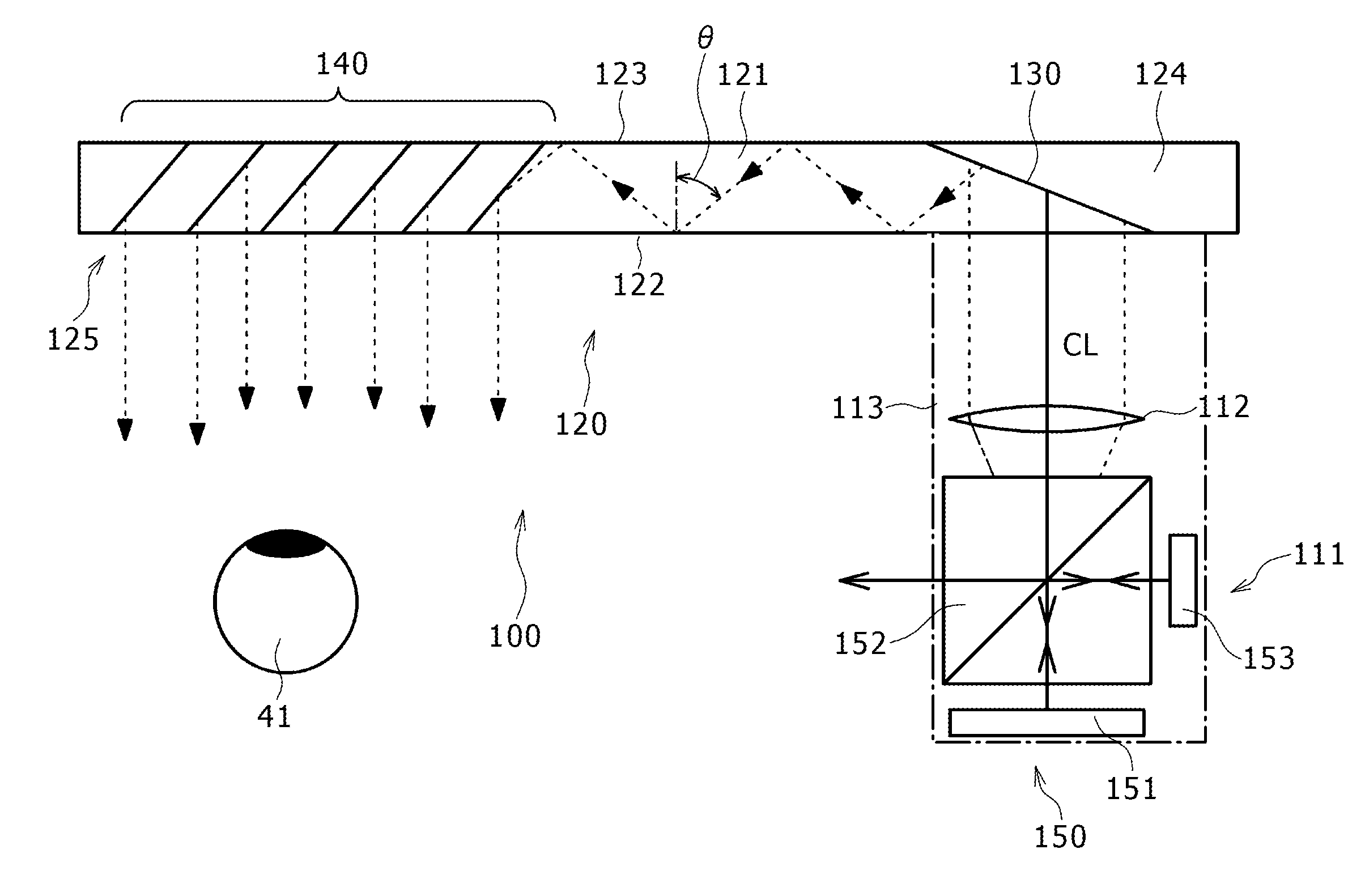
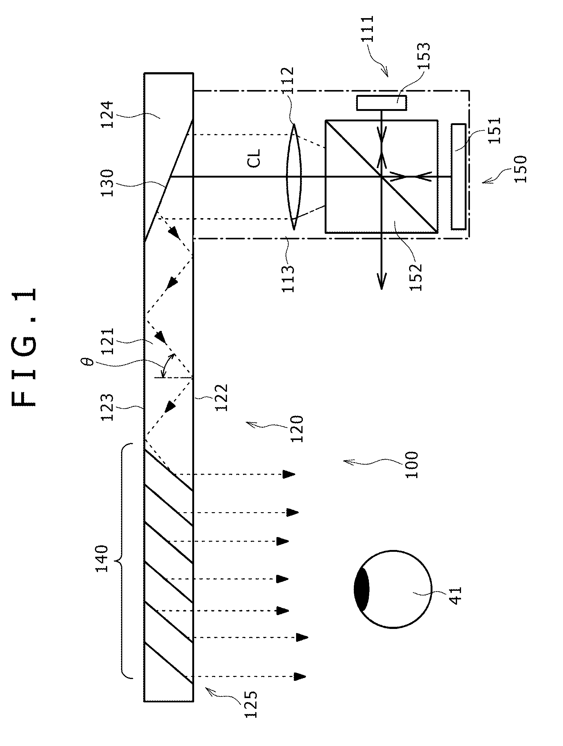
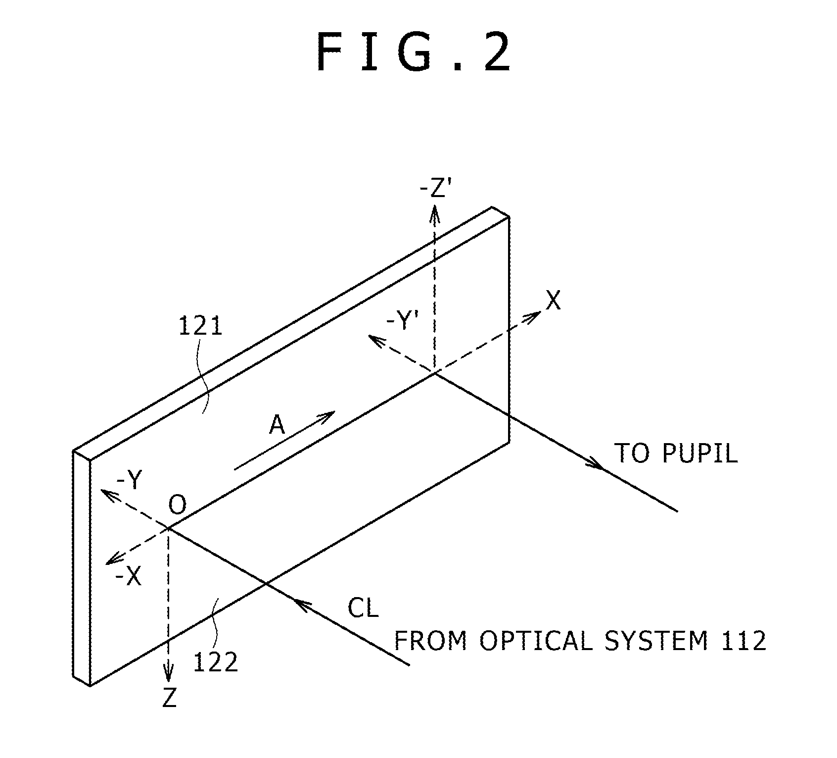
[0174]A working example 1 relates to an image displaying method for a head-mounted type display unit according to a first embodiment of the present invention. It is to be noted that, in the following description, the “image displaying method for a head-mounted type display unit” is referred to simply as “image display method.” A schematic view showing an image display apparatus of the head-mounted type display unit according to the working example 1 is shown in FIG. 1. Meanwhile, a schematic view illustrating propagation of light in and around a light guide plate which configures the image display apparatus in the head-mounted type display unit of the working example 1 is shown in FIG. 2. A schematic view of the head-mounted type display unit as viewed from above is shown in FIG. 3. A schematic view of the head-mounted type display unit as viewed from a side is shown in FIG. 4. Further, a schematic view of the head-mounted type display unit of the working example 1 as viewed from th...

working example 2

[0213]The working example 2 is a modification to the image display apparatus according to the working example 1. Referring to FIGS. 14 and 16 which schematically show the image display apparatus 200 or 400 of the head-mounted type display unit of the working example 2 and the working example 4 which is hereinafter described, the image forming apparatus 211 is configured from an image forming apparatus of a second configuration. In particular, the image forming apparatus 211 includes a light source 251, and a scanning section 253 for scanning parallel light emitted from the light source 251. More particularly, the image forming apparatus 211 includes:

[0214]a light source 251;

[0215]a collimate optical system 252 for converting light emitted from the light source 251 into parallel light;

[0216]a scanning section 253 configured to scan the parallel light outputted from the collimate optical system 252; and

[0217]a relay optical system 254 for relaying and outputting the parallel light sca...

working example 3

[0221]Also the working example 3 is a modification to the image display apparatus in the working example 1. The image display apparatus 300 in the head-mounted type display unit of the working example 3 is schematically shown in FIG. 15A. Meanwhile, a cross section of part of a reflection type volume hologram diffraction grating used in the image display apparatus 300 is schematically shown in FIG. 15B. In the working example 3, the image forming apparatus 111 is configured from an image forming apparatus of the first configuration similarly as in the working example 1. Meanwhile, the optical apparatus 320 is similar in basic configuration and structure to the optical apparatus 120 in the working example 1 except that the first and second deflection sections are different in configuration and structure.

[0222]Referring to FIGS. 15A and 15B, in the working example 3, the first and second deflection sections are disposed on the surface of the light guide plate 321, particularly on the ...


PUM


Abstract

Disclosed herein is an image displaying method for a head-mounted type display unit which includes a frame of the glasses type for being mounted on the head of an observer, an image display apparatus attached to the frame, and a control section for controlling image display of the image display apparatus. The image display apparatus includes an image forming apparatus, and an optical apparatus. The image displaying method includes the steps of: storing a data group configured from a plurality of data in a storage section; adding a data identification code to each of the data; sending a designation identification code and display time information at predetermined intervals of time; and reading out the data whose data identification code coincides with the received designation identification code from the storage section and controlling the image forming apparatus to display an image based on the read out data.

Description

BACKGROUND OF THE INVENTION[0001]1. Field of the Invention[0002]This invention relates to an image displaying method for a head-mounted type display unit (HMD: Head Mounted Display).[0003]2. Description of the Related Art[0004]A virtual image display apparatus for allowing an observer to observe a two-dimensional image formed by an image forming apparatus as an enlarged virtual image by means of a virtual image optical system is known and disclosed, for example, in Japanese Patent Laid-Open No. 2006-162767 (referred to as Patent Document 1 hereinafter).[0005]FIG. 1 schematically shows the image display apparatus mentioned above. Referring to FIG. 1, the image display apparatus 100 shown includes an image forming apparatus 111 including a plurality of pixels arrayed in a two-dimensional matrix, a collimate optical system 112 for converting light outputted from the pixels of the image forming apparatus 111 into parallel light, and an optical apparatus or a light guide section 120 to w...

Claims


Application Information

Patent Timeline
Patent Type & Authority Applications(United States)
IPC IPC(8): G09G5/00
CPCG02B6/00G02B27/017G06T19/006G02B2027/0178G06F3/011G02B2027/014
Inventor CHOSOKABE, YOSHIHIROMATSUMURA, IKUO
Owner SONY CORP
Why Eureka
Try Eureka