
Creation of depth maps from images

a depth map and image technology, applied in image analysis, image enhancement, instruments, etc., can solve the problems of difficult estimation in the air, inability to correctly place the depth map on the 3d model, and less effective approach

Active Publication Date: 2011-10-13
KONINKLIJKE PHILIPS ELECTRONICS NV
View PDF1 Cites 26 Cited by
  • Summary
  • Abstract
  • Description
  • Claims
  • Application Information

AI Technical Summary

Benefits of technology

[0013]Owing to the invention, it is possible to provide a solution for generating a depth map from an image which has increased robustness and stability by working with different schemas using depth models of varying complexity (for example, constant depth, sloping depth, or sloping depth with player segmentation). By obtaining information relating to the shot defined in each image, this information can be used as a trigger to switch schema. A schema, in its simplest implementation, is a depth model, which specifies one or more depth profiles for the ultimate depth map. A simple schema might be a depth model that specifies a single constant depth throughout a depth map. A more complex schema might be one that specifies a simple gradient over the depth map, and a yet more complex schema might specify a gradient plus the detection of one or multiple players (through segmentation for example). When a defined circumstance arises, such as the confidence in a scenario being too low, the algorithm automatically switches back to a lower (simpler) scenario (depth model) for which accurate reconstruction is possible. For example, if the player segmentation has a low confidence, only the field model is used, without player segmentation.
[0016]Advantageously, the method comprises accessing first and second depth models, wherein the first schema comprises the first depth model, and the second schema comprises the second model. This is the simplest implementation of the new system, which uses two models, and switches between the models when the shot change has been detected. In a second embodiment, also using first and second depth models, the first schema comprises the first depth model, and the second schema comprises a combination of the first and the second depth models. In this way, a sudden change in the depth map is avoided, and a mix of the models is used to create the second schema.
[0017]In the second embodiment, preferably the method includes setting a mix factor according to the number of images since the first schema alone was last used to generate a depth map, the mix factor determining the relative contributions of the first and the second depth models. The use of a mix factor that is set based on the number of images since the change to the second schema was initiated ensures a smooth transition from one schema to the second schema.

Problems solved by technology

Such an approach is less effective when very few lines (or no lines at all) are visible in a view.
The position of the ball can be easily estimated when it is on the ground, but is difficult to estimate in the air.
If a player is not detected, he cannot be placed correctly on the 3D model.
This diminishes the depth effect, and gives a local distortion, but it does not create artefacts such as when a full 3D model is reconstructed.
The main problem with the existing methods is their failure for specific types of scenes.
As described above, the camera calibration works well for scenes containing the goal, but performs much worse when a central part of the field is captured.
Another problem of the existing methods is that they sometimes require setups with special cameras, for which costly adaptations to the capturing infrastructure need to be made.
The focus in the prior art algorithms is on producing correct 3D models, not on the 3D impression and robustness.

Method used


Image

  • Creation of depth maps from images
  • Creation of depth maps from images
  • Creation of depth maps from images

Examples


Embodiment Construction

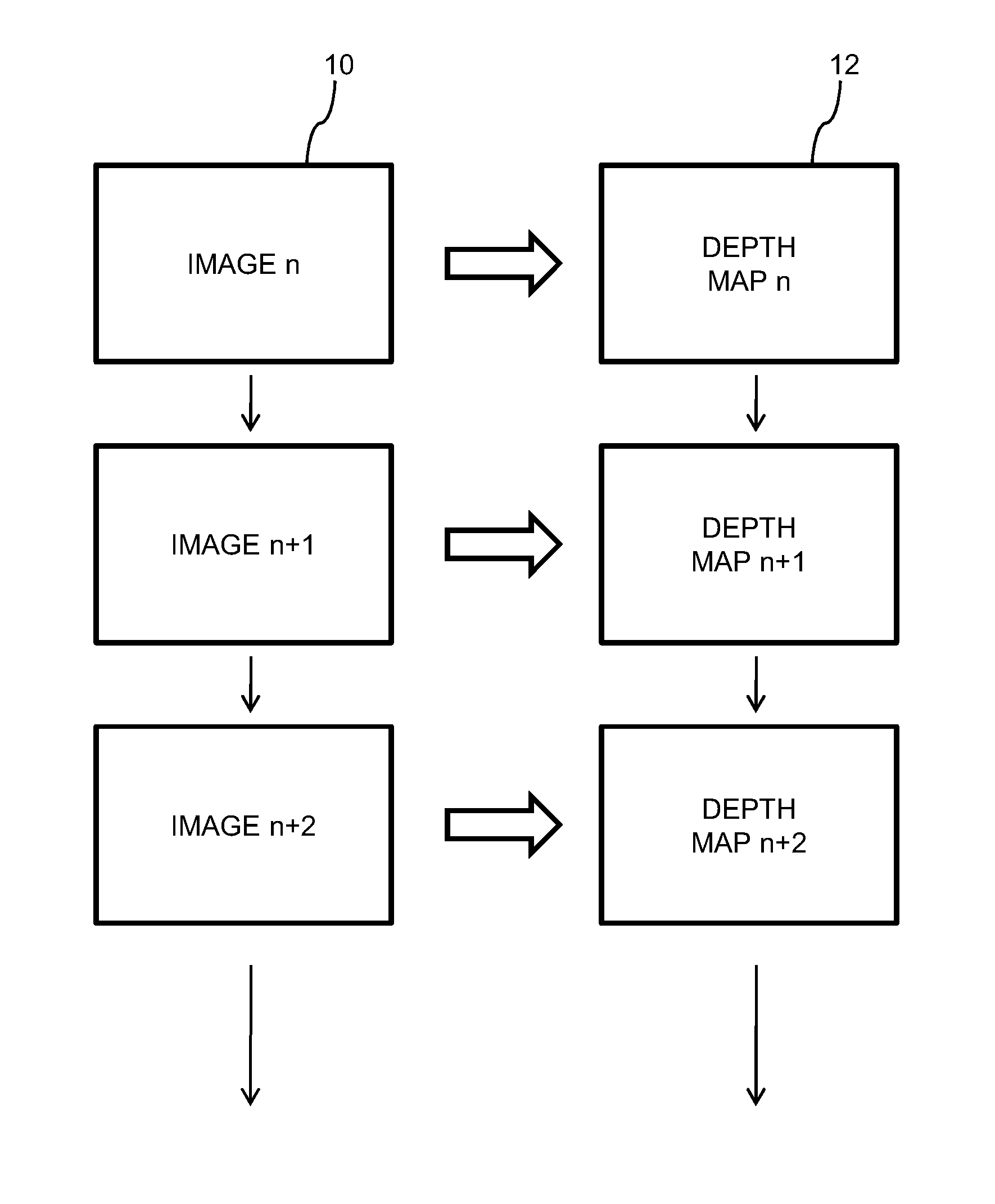
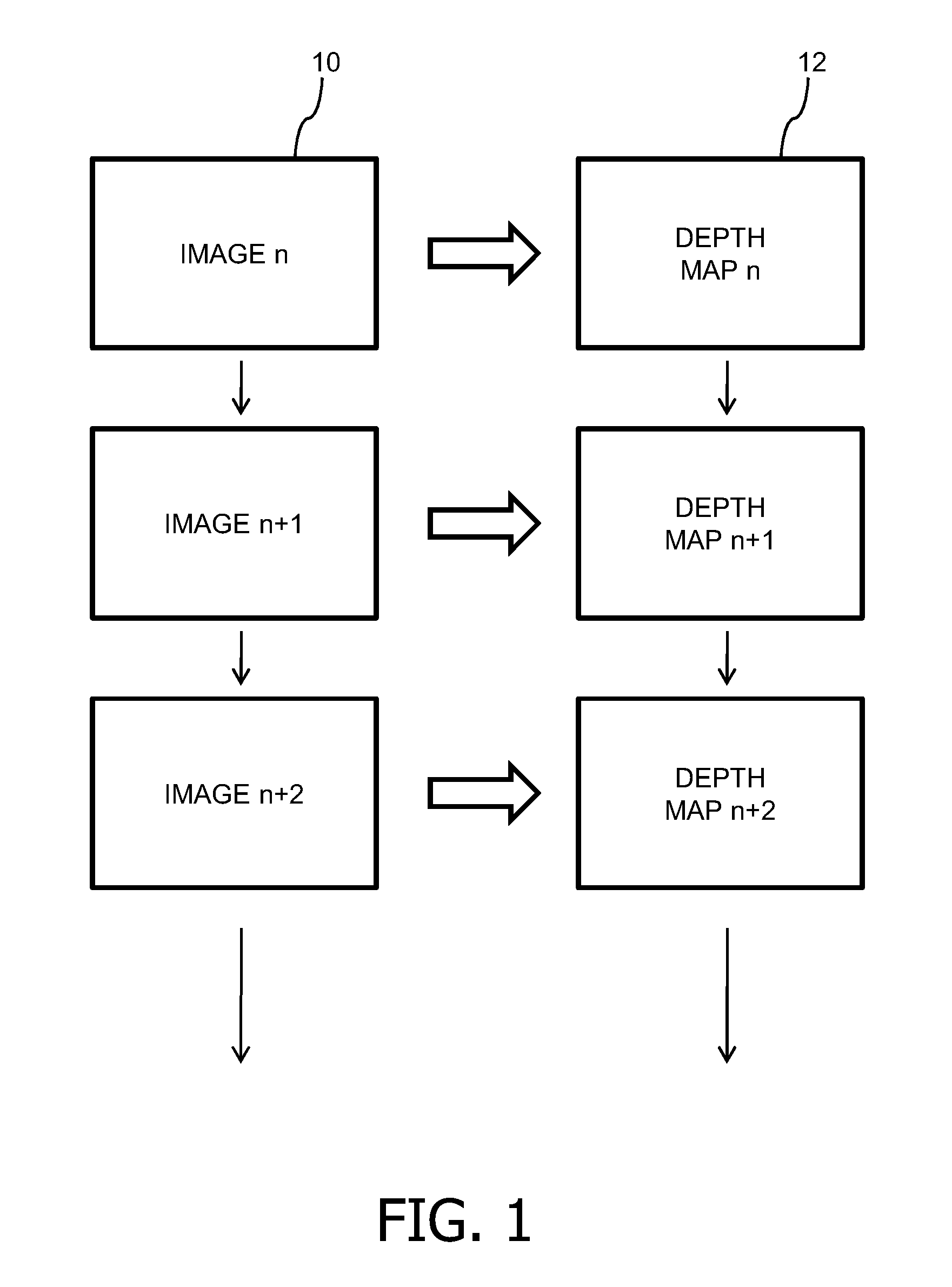
[0035]The basic principle is illustrated in FIG. 1. Video to be displayed comprises a series of images 10 also referred to as frames in many situations, which are used to generate a corresponding series of depth maps 12, each image 10 having a respective depth map 12. The generation of the depth map supports the generation of a 3D image at the ultimate display device, from the original 2D format, which is represented by the series of images 10. A depth map 12 can be used to generate one or more additional images that are then used, along with the original image 10, in an autostereoscopic or stereoscopic display device. A depth map 12 can also be used to generate a disparity map, if that is needed by the specific 3D application.

[0036]As discussed above, in respect of the prior art cited in the references, the generation of such depth maps 12 from source images 10 is well known. The present invention provides an improvement in the method of generating the depth maps 12, in order to pr...


PUM


Abstract

A method of generating a plurality of depth maps for a plurality of images comprises receiving a first image, obtaining information relating to the shot defined by the first image, generating a depth map for the first image according to a first schema, receiving a second image, obtaining information relating to the shot defined by the second image, detecting a change in the obtained information between the first and second image, and generating a depth map for the second image according to a second schema, the second schema having a complexity different from that of the first schema. The method can comprise accessing first and second depth models. In one embodiment, the first schema comprises the first depth model, and the second schema comprises the second model, and in a second embodiment the first schema comprises the first depth model, and the second schema comprises a combination of the first and the second depth models.

Description

FIELD OF THE INVENTION[0001]This invention relates to a method of, and system for, generating a plurality of depth maps for a plurality of images. In one embodiment, this can be used in the automatic depth estimation for soccer video.BACKGROUND OF THE INVENTION[0002]It is likely that in the near future three-dimensional (3D) display devices will become increasingly common in home and business environments. Such devices are either stereoscopic, which require the user to wear special glasses to see the 3D image, or autostereoscopic, which do not require any special glasses in order to see the 3D image. To create a 3D image, two different 2D images are needed, that are provided one to left eye of the user and one to the right eye of the user. It is also sufficient to provide a single image and either an additional depth map or disparity map, which contains sufficient information to allow the second image to be generated. This latter solution has a number of advantages because it allows...

Claims


Application Information

Patent Timeline
IPC IPC(8): H04N13/02G06K9/00
CPCG06T7/0065G06T2207/30228G06T2207/10021G06T2207/10012G06T7/55G06T7/50G06T15/20G06T15/205G06T17/00H04N13/00
Inventor VANDEWALLE, PATRICK LUC E.VAREKAMP, CHRISTIAANKLEIN GUNNEWIEK, REINIER BERNARDUS MARIA
Owner KONINKLIJKE PHILIPS ELECTRONICS NV
Learn More