Application of blend zones, depth reduction, and transition zones to ablation shapes

a technology of blend zone and transition zone, applied in the field of laser eye surgery, can solve the problems of not being able or desirable to follow known ablation profiles, not being able to achieve the effect of enhancing flap positioning, reducing the incidence of night vision problems, and enhancing the angl

Active Publication Date: 2012-10-25
AMO MFG USA INC
View PDF8 Cites 17 Cited by
  • Summary
  • Abstract
  • Description
  • Claims
  • Application Information

AI Technical Summary

Benefits of technology

[0010]The present invention provides improved laser-based methods and systems for correction of vision defects. These systems and methods may be particularly useful for treating patients presenting certain anatomical features, such as large pupil diameters or thin corneal tissue. Advantageously, these techniques generally avoid abrupt changes in ablation depth of the ablation profile, and particularly toward the peripheral areas of the ablation. The form of the ablation profile can vary, depending in part on the type of refractive treatment being administered. The systems and methods of the present invention also are advantageous because they provide ablation zones having decreased angles at the ablation edge; they may reduce incidence of night vision problems, and they may enhance flap positioning and fit in a LASIK procedure. The present invention may be used to treat a wide variety of optical conditions, including, but not limited to, myopia, hyperopia, presbyopia, astigmatism, and irregular astigmatism. To achieve these advantages, the present invention often provides for the incorporation of depth reduction, blend region, and transition region features into treatment ablation profiles to more efficiently and effectively help patients who have heretofore been particularly difficult and / or impossible to treat with conventional techniques.
[0015]The method of the present invention may further include determining the first ablation profile in response to a size of an optical zone of the eye and an optical power correction. Treatment of the cornea with the depth reduced ablation profile can establish in the cornea an optically correct central optical zone and a blend zone peripheral to the central optical zone, wherein the blend zone may be at least partially within the optical zone of the eye. The optical power of the blend zone can gradually diminish with increasing radius from the central optical zone.
[0020]In a fourth aspect, the present invention can provide a method for reprofiling a surface of a cornea of an eye by ablating a portion of the cornea to create an ablation zone that provides an ablation surface. The ablation zone may include an ablated central optical zone disposed in a central portion of the cornea, wherein the central optical zone provides an optically correct central optical surface. The optical zone may further include an ablated blend zone disposed peripherally to the ablated central optical zone and at least partially within an optical zone of the eye. Respectively, the optical zone may provide an optical surface, and the ablated blend zone may provide a blend surface. The blend surface can be disposed peripherally to the central optical surface and at least partially within the optical surface of the eye, and can have an optical power that gradually diminishes as a function of increasing radius out toward an ablation surface edge. Additionally, the ablation zone may also include a transition zone disposed peripherally to the blend zone, between an interface with the blend zone and an ablation zone edge. The transition zone can provide a transition surface, the. transition surface being disposed peripherally to the blend surface and an ablation surface edge.

Problems solved by technology

Many patients suffer from optical defects that are not easily treated using known corneal reshaping ablation techniques, and in certain circumstances it may not be possible or desirable to follow known ablation profiles.
Standard ablation profiles may also be inappropriate for a patient having an unusually thin cornea.
Belatedly, there are circumstances where standard ablation profiles may be inappropriate for a patient as known shapes may introduce or amplify night glare problems.
Likewise, certain currently used ablation profiles may complicate flap repositioning procedures.

Method used


Image

  • Application of blend zones, depth reduction, and transition zones to ablation shapes
  • Application of blend zones, depth reduction, and transition zones to ablation shapes
  • Application of blend zones, depth reduction, and transition zones to ablation shapes

Examples


Embodiment Construction

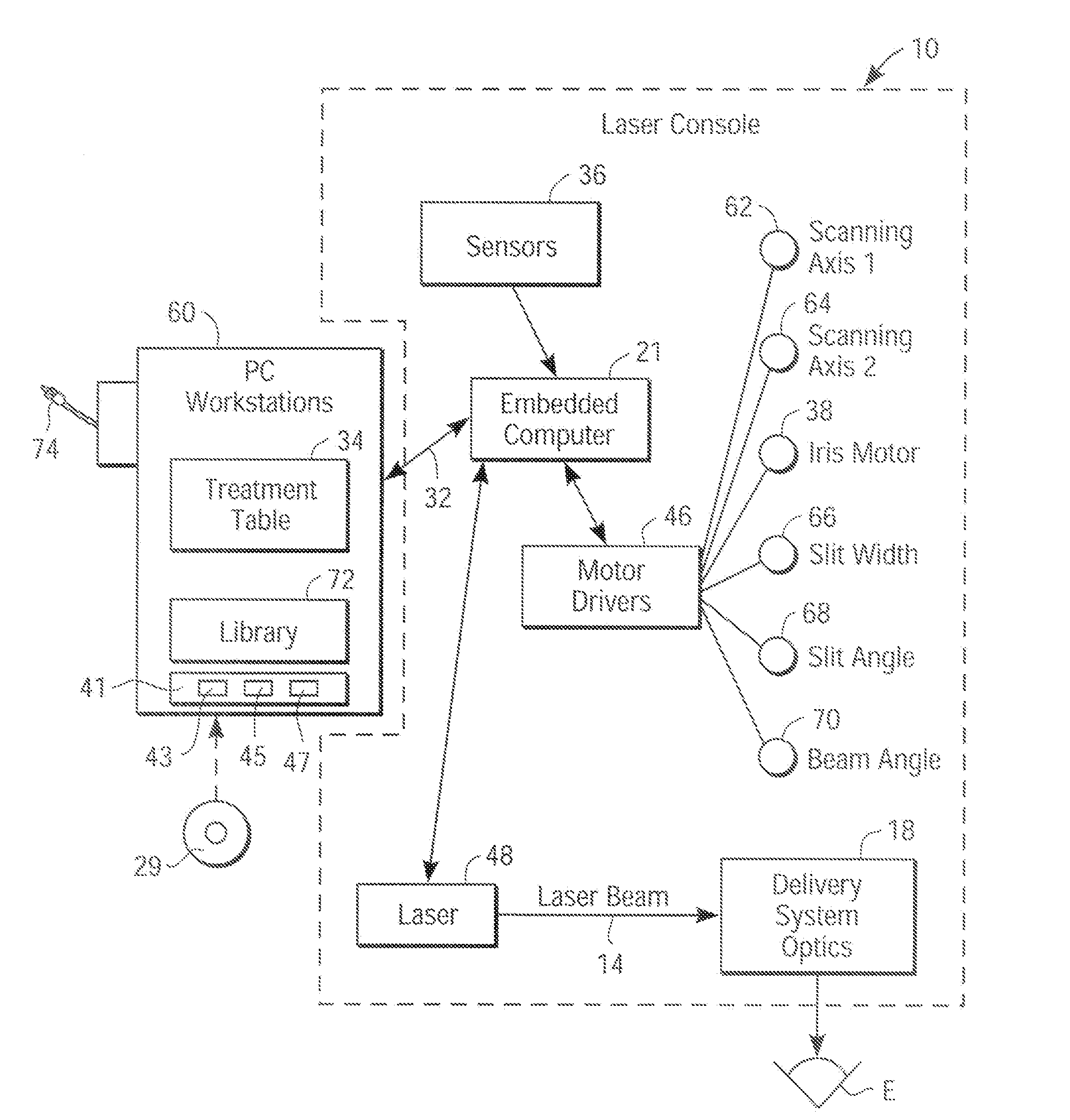
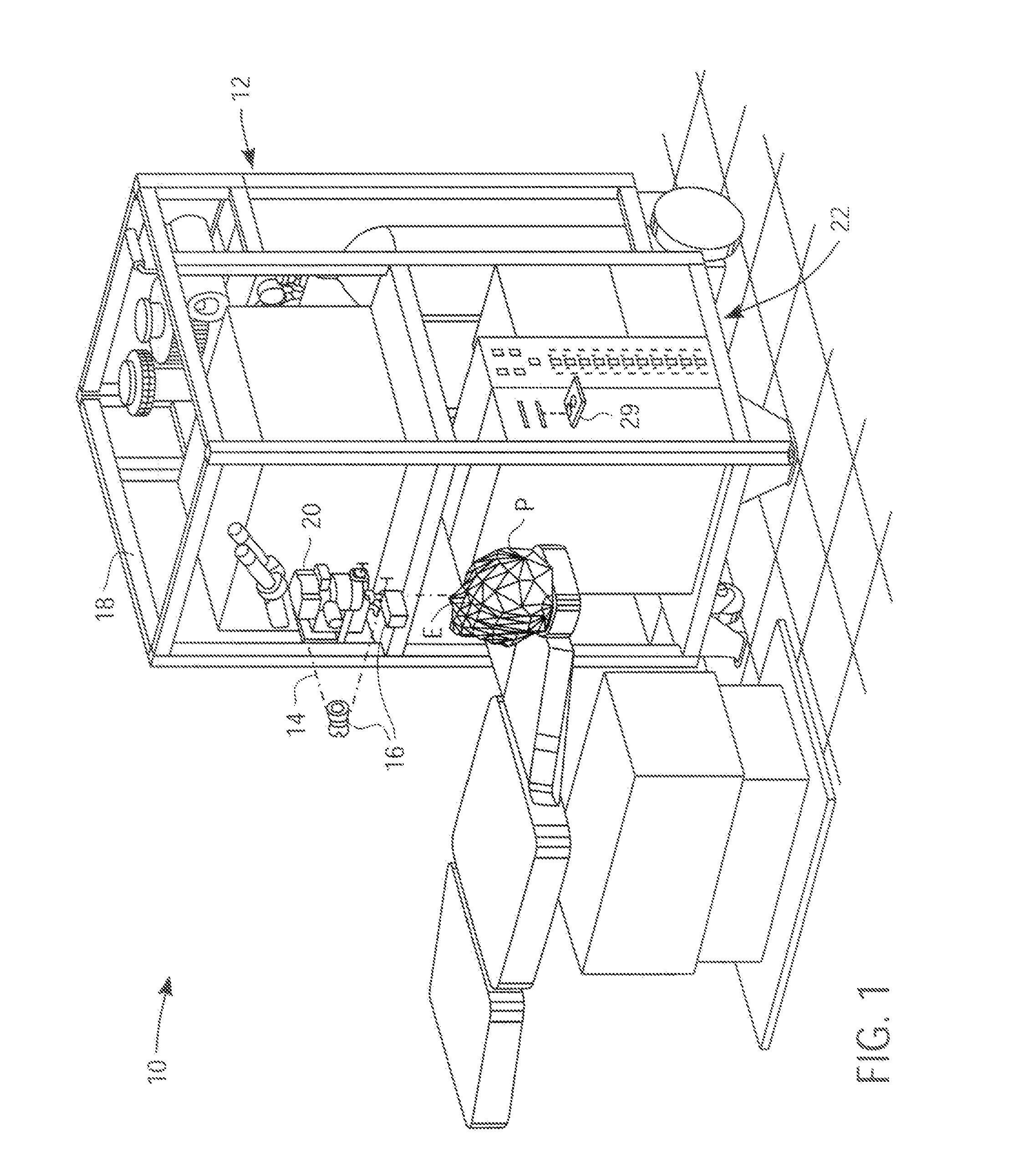
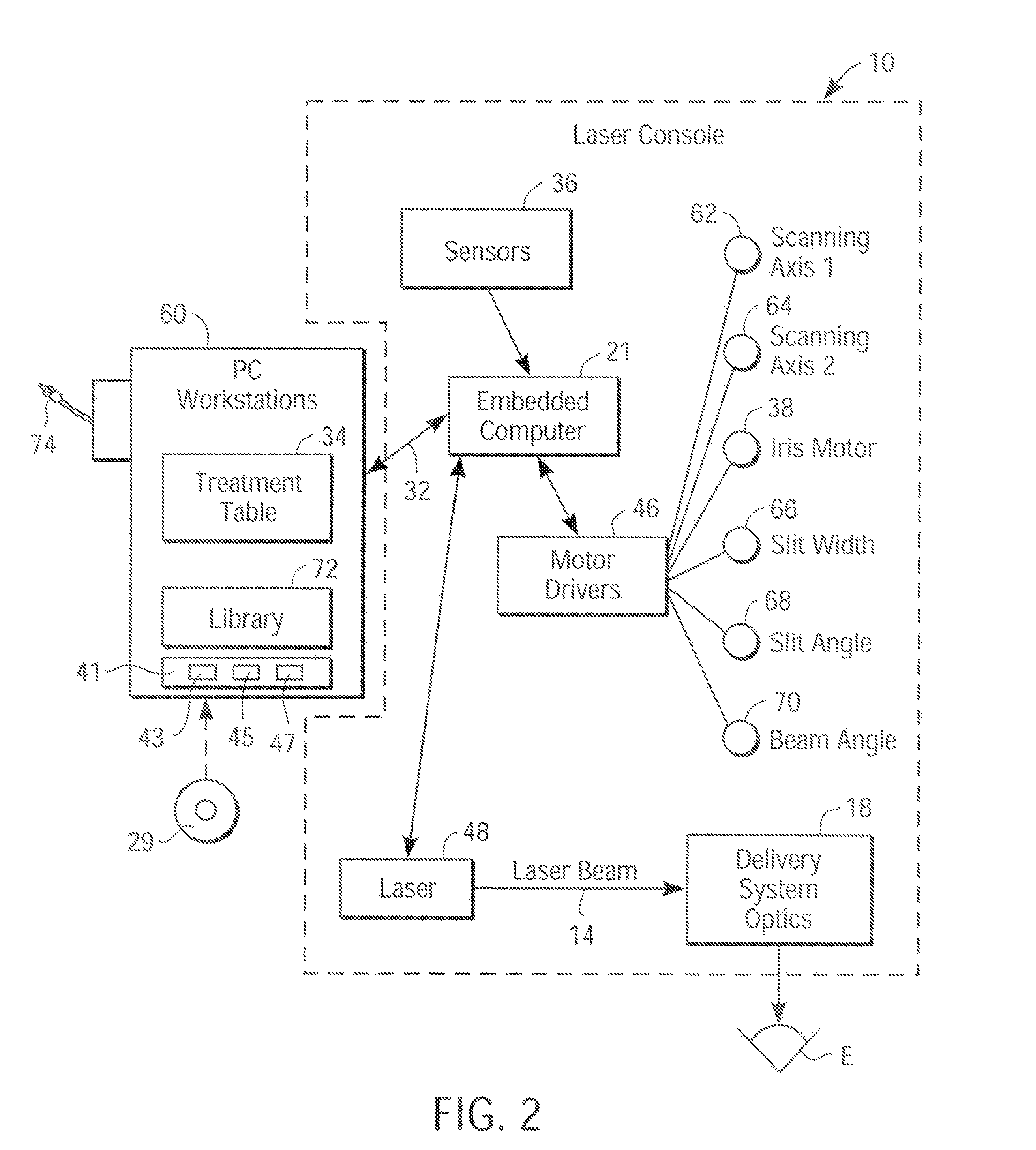
[0034]The present invention is particularly useful for enhancing the accuracy and efficacy of laser eye surgical procedures, such as photorefractive keratectomy (PRK), phototherapeutic keratectomy (PTK), laser in situ keratomileusis (LASIK), laser assisted epithelium keratomileusis (LASEK), and the like. Preferably, the present invention can provide enhanced refractive procedures by improving the methodology for deriving or generating a corneal ablation profile.

[0035]While the system and methods of the present invention are described primarily in the context of a laser eye surgery system, it should be understood that the techniques of the present invention may be adapted for use in alternative eye treatment procedures and systems such as radial keratotomy (e.g., by attenuating an incision depth at the periphery of a radial keratotomy incision), intraocular lenses, collagenous corneal tissue thermal remodeling, removable corneal lens structures, and the like.

[0036]According to the pr...


PUM


Abstract

Methods, devices, and systems for reprofiling a surface of a cornea of an eye ablate a portion of the cornea to create an ablation zone with an optically correct central optical zone disposed in a central portion of the cornea, and a blend zone disposed peripherally to the central optical zone and at least partially within an optical zone of the eye. The blend zone can have an optical power that gradually diminishes with increasing radius from the central optical zone.

Description

CROSS-REFERENCES TO RELATED APPLICATIONS[0001]This application is a continuation of U.S. patent application Ser. No. 10 / 100,231 filed Mar. 14, 2002. entitled “APPLICATION OF BLEND ZONES, DEPTH REDUCTION AND TRANSITION TO ZONES TO ABLATION SHAPES,”which is incorporated herein by reference for all purposes.STATEMENT AS TO RIGHTS TO INVENTIONS MADE UNDER FEDERALLY SPONSORED RESEARCH OR DEVELOPMENT[0002]Not applicableREFERENCE TO A “SEQUENCE LISTING,” A TABLE, OR A COMPUTER PROGRAM LISTING APPENDIX SUBMITTED ON A COMPACT DISK.[0003]Not applicableBACKGROUND OF THE INVENTION[0004]This invention generally relates to laser eye surgery, and in particular provides methods, devices, and systems for selectively ablating corneal tissue to improve the vision of patients having corneal irregularities or other vision defects.[0005]There arc known laser-based systems and methods for enabling ophthalmic surgery on the cornea in order to treat vision defects. Typically, these systems and methods perfo...

Claims


Application Information

Patent Timeline
Patent Type & Authority Applications(United States)
IPC IPC(8): A61F9/01A61FA61F9/007
CPCA61F9/008A61F9/00806A61F9/00808A61F9/00817A61F2009/0088A61F2009/00846A61F2009/00848A61F2009/00872A61F2009/00844
Inventor GROSS, ERIKHOFER, RICHWONG, JONATHAN
Owner AMO MFG USA INC
Why Eureka
Try Eureka