Exposure control using digital radiography detector

a digital radiography and detector technology, applied in the field of radiographic imaging, can solve the problems of less accurate detection of the exposure level, risk of over- or under-exposure, and present problems, and achieve the effect of greater flexibility in the us

a digital radiography and detector technology, applied in the field of radiographic imaging, can solve the problems of less accurate detection of the exposure level, risk of over- or under-exposure, and present problems, and achieve the effect of greater flexibility in the us

US20110249791A1Active Publication Date: 2011-10-13CARESTREAM HEALTH INC

Image

  • Exposure control using digital radiography detector
  • Exposure control using digital radiography detector
  • Exposure control using digital radiography detector

Examples


Embodiment Construction

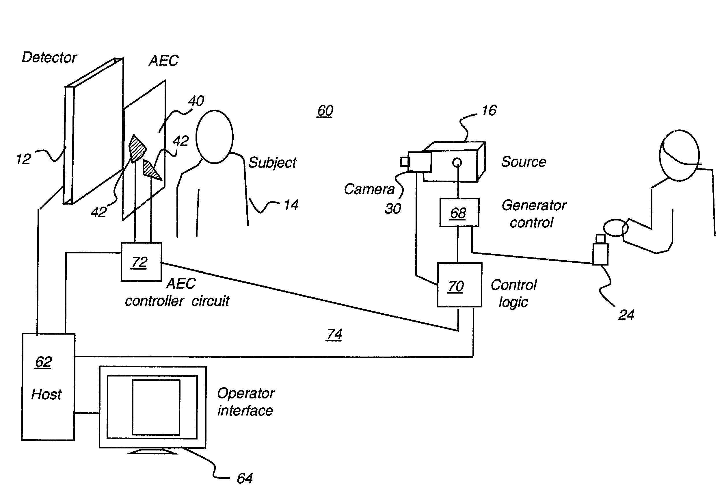
[0046]The following is a detailed description of the preferred embodiments of the invention, reference being made to the drawings in which the same reference numerals identify the same elements of structure in each of the several figures.

[0047]In the context of the present disclosure, the use of terms such as “first”, “second”, “third”, etc., does not by itself connote any priority, precedence, or order of a component or claim element over another or the temporal order in which acts of a method are performed. These terms may be used more generally as labels to distinguish one element having a certain name from another element having the same name (but for use of the ordinal term) or to distinguish the claim elements.

[0048]The term “set”, as used herein, refers to a non-empty set, as the concept of a collection of elements or members of a set is widely understood in elementary mathematics. The term “subset”, unless otherwise explicitly stated, is used herein to refer to a non-empty p...


PUM


Abstract

A method for sensing a level of ionizing radiation directed from a radiation source through a subject and toward a digital radiography detector, executed at least in part by a logic processor, obtains image data that relates the position of the subject to the digital radiography detector and assigns one or more radiant-energy sensing elements of the digital radiography detector as one or more exposure control sensing elements. The one or more exposure control sensing elements are sampled one or more times during exposure to measure the exposure directed to the subject. A signal is provided to terminate exposure according to exposure measurements obtained from the one or more exposure control sensing elements within the digital radiography detector.

Description

CROSS REFERENCE TO RELATED APPLICATION[0001]This application claims priority to Provisional Application Ser. No. 61 / 323,476, filed 13 Apr. 2010, entitled “MOBILE UNIT HAVING TUBE ALIGNMENT SYSTEM,” by Lalena, incorporated herein by reference.[0002]This application claims priority to Provisional Application Ser. No. 61 / 449,932, filed 7 Mar. 2011, entitled “GRAPHIC USER INTERFACE FOR MOBILE UNIT,” by Stagnitto, incorporated herein by reference.[0003]This application relates to patent application U.S. Ser. No. ______ entitled “CONFIGURABLE AEC SENSOR FOR AN X-RAY SYSTEM” in the name of Lalena, filed on even date.[0004]This application relates to patent application U.S. Ser. No. ______ entitled “DISPLAY OF AEC SENSOR LOCATION” in the name of Wang, filed on even date.FIELD OF THE INVENTION[0005]The invention relates generally to the field of radiographic imaging and more particularly relates to apparatus and methods for control of exposure energy in an X-ray system.BACKGROUND OF THE INVE...

Claims


Application Information

Patent Timeline
13 Oct 2011
Publication
US20110249791A1
IPC
A61B6/10
CPC
A61B6/08; A61B6/4208; A61B6/4266; A61B6/4405; A61B6/461; A61B6/542; A61B6/547; A61B6/587
Inventors
WANG, XIAOHUI; FOOS, DAVID H.