Radial pre-swirl assembly and cooling fluid metering structure for a gas turbine engine

a gas turbine engine and cooling fluid technology, applied in the direction of liquid fuel engines, machines/engines, mechanical equipment, etc., can solve the problems of reduced engine output and increased cooling air temperatur

Active Publication Date: 2011-10-13
SIEMENS ENERGY INC
View PDF11 Cites 32 Cited by
  • Summary
  • Abstract
  • Description
  • Claims
  • Application Information

AI Technical Summary

Benefits of technology

[0005]In accordance with a first aspect of the present invention, a gas turbine engine is provided having a central axis defining an axial direction. The engine comprises a supply of cooling fluid, a rotatable shaft extending in the axial direction of the engine, and shaft cover structure disposed about the shaft such that a flow path extends in the axial direction between the shaft and the shaft cover structure. The engine further comprises pre-swirl structure coupled to the shaft cover structure and located radially between the supply of cooling fluid and the flow path, the pre-swirl structure extending in a circumferential direction about the shaft. The pre-swirl structure comprises forward wall structure and aft wall structure spaced in the axial direction from the forward wall structure. The forward and aft wall structures define a flow passage therebetween, the flow passage including an inlet in communication with the supply of cooling fluid and an outlet in communication with the flow path. The flow passage supplies a first portion of cooling fluid from the supply of cooling fluid to the flow path. The pre-swirl structure further comprises a plurality of swirl members in the flow passage extending between the forward and aft wall structures. Each swirl member includes a leading edge and a trailing edge spaced from the leading edge in a radial direction, wherein the trailing edge is offset from the leading edge in the circumferential direction. A flow direction of the first portion of cooling fluid passing through the flow passage is altered by the swirl members such that the first portion of cooling fluid has a velocity component in a direction tangential to the circumferential direction when the first portion of cooling fluid enters the flow passage. The engine also comprises at least one bypass passage defined through the shaft cover structure and including an exit opening at an end of the shaft cover structure. The at least one bypass passage receives a second portion of cooling fluid from the supply of cooling fluid and supplies the second portion of cooling fluid to a turbine rim cavity associated with a first row vane assembly to prevent hot gas ingestion into the turbine rim cavity from a hot gas flow path associated with a turbine section of the engine.

Problems solved by technology

The rotating components associated with the rotor may be moving at a substantially higher speed than the cooling air supplied for cooling the components such that the cooling air may produce a drag force on the rotating components, which may result in reduced output of the engine and an increased temperature of the cooling air.

Method used


Image

  • Radial pre-swirl assembly and cooling fluid metering structure for a gas turbine engine
  • Radial pre-swirl assembly and cooling fluid metering structure for a gas turbine engine
  • Radial pre-swirl assembly and cooling fluid metering structure for a gas turbine engine

Examples


Embodiment Construction

[0017]In the following detailed description of the preferred embodiments, reference is made to the accompanying drawings that form a part hereof, and in which is shown by way of illustration, and not by way of limitation, specific preferred embodiments in which the invention may be practiced. It is to be understood that other embodiments may be utilized and that changes may be made without departing from the spirit and scope of the present invention.

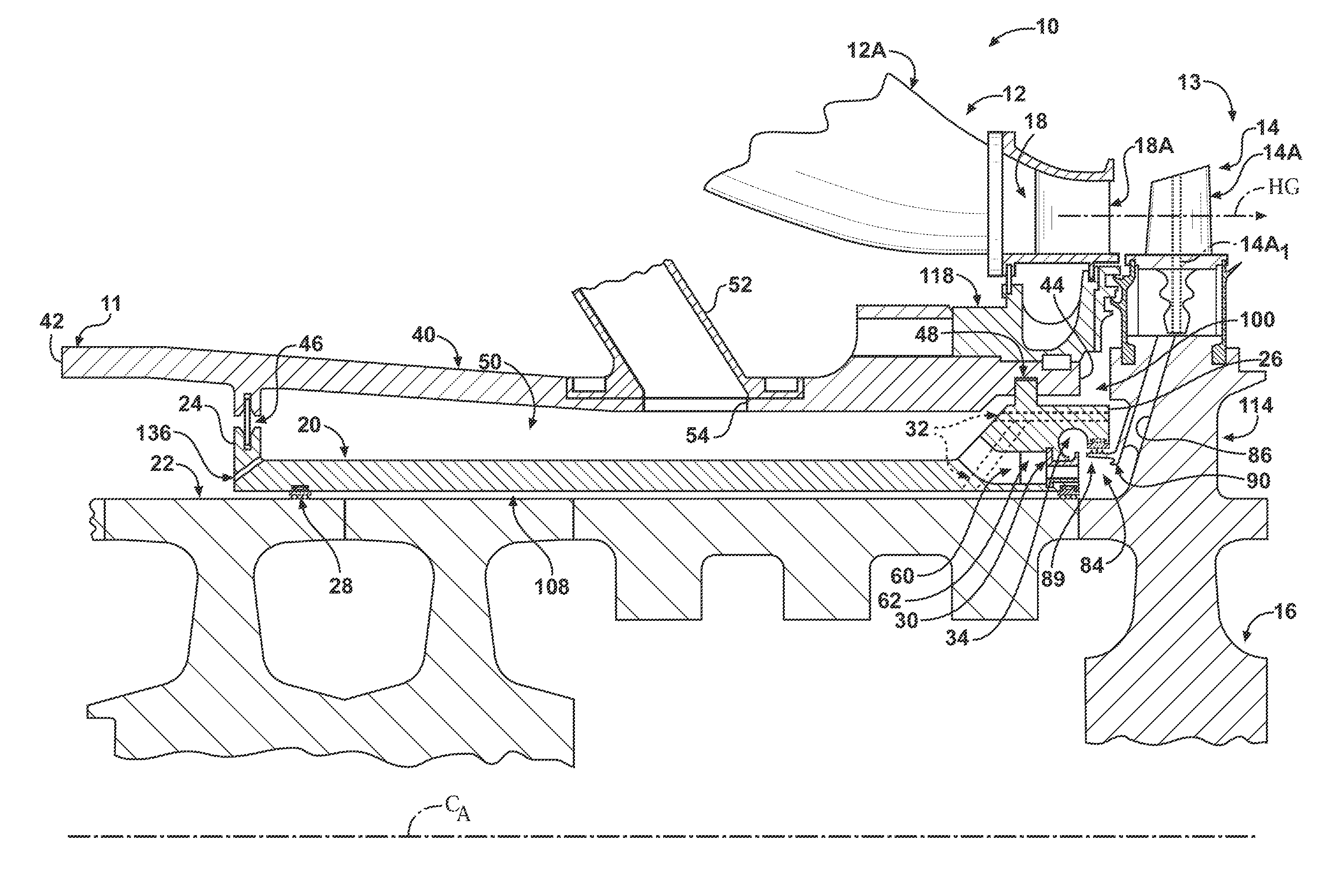
[0018]Referring now to FIG. 1, a portion of a gas turbine engine 10 according to an embodiment of the invention is shown. The engine 10 includes a conventional compressor section 11 for compressing air. The compressed air from the compressor section 11 is conveyed to a combustion section 12, which produces hot combustion gases by burning fuel in the presence of the compressed air from the compressor section 11. The combustion gases are conveyed through a plurality of transition ducts 12A to a turbine section 13 of the engine 10. The turb...


PUM


Abstract

A gas turbine engine comprises a pre-swirl structure coupled to a shaft cover structure and located radially between a supply of cooling fluid and a flow path. The pre-swirl structure defines a flow passage and includes a plurality of swirl members in the flow passage. A flow direction of cooling fluid passing through the flow passage is altered by the swirl members such that the cooling fluid has a velocity component in a direction tangential to the circumferential direction. The bypass passages provide cooling fluid into a turbine rim cavity associated with a first row vane assembly to prevent hot gas ingestion into the turbine rim cavity from a hot gas flow path associated with a turbine section of the engine.

Description

CROSS REFERENCE TO RELATED APPLICATIONS[0001]This application is a Continuation-In-Part of U.S. patent application Ser. No. 12 / 758,069, (Attorney Docket No. 2010P00100US), filed Apr. 12, 2010, entitled “COOLING FLUID METERING STRUCTURE IN A GAS TURBINE ENGINE” by Keith D. Kimmel et al., the entire disclosure of which is incorporated by reference herein.FIELD OF THE INVENTION[0002]The present invention relates to gas turbine engines, and more particularly, to a gas turbine engine including a radial pre-swirl assembly and a metering structure associated with a plurality of bypass passages.BACKGROUND OF THE INVENTION[0003]In gas turbine engines, compressed air discharged from a compressor section and fuel introduced from a source of fuel are mixed together and burned in a combustion section, creating combustion products defining hot working gases. The working gases are directed through a hot gas path in a turbine section, where they expand to provide rotation of a turbine rotor. The tu...

Claims


Application Information

Patent Timeline
Patent Type & Authority Applications(United States)
IPC IPC(8): F01D5/08
CPCF01D5/081F01D5/082F02C7/28F05D2250/322F05D2260/20F05D2260/2212F05D2260/60
Inventor LAURELLO, VINCENT P.KIMMEL, KEITH D.EBERT, TODD
Owner SIEMENS ENERGY INC
Why Eureka
Try Eureka