
Circular Saw with Anti-Splinter Device

a technology of anti-splinter and circular saw, which is applied in the direction of metal sawing devices, metal sawing accessories, manufacturing tools, etc., can solve the problems of operator injury and sawing malfunction, and achieve the effect of preventing chips from splashing, clear line of sight, and small distan

Inactive Publication Date: 2011-10-20
BOSCH POWER TOOLS CHINA +1
View PDF6 Cites 9 Cited by
  • Summary
  • Abstract
  • Description
  • Claims
  • Application Information

AI Technical Summary

Benefits of technology

[0004]An object of the present invention is to provide a circular saw with an improved anti-splinter device for preventing chip splintering during the operation of the saw and providing a safe and comfortable working environment to operators.
[0005]For achieving this task, according to one aspect of the invention, a circular saw comprises a base plate defining a base plane; a bevel bracket which supports a circular saw blade and is pivotably mounted on the base plate for tilting the blade, the bevel bracket having a pivoting axis which is substantially parallel to the base plane and the blade and substantially perpendicular to a rotational axis of the blade, and the blade partly extending through an opening formed in the base plate; and an anti-splinter device for preventing cutting chips from splintering out of the opening during the operation of the saw and comprising: a pair of slides mounted in the opening and forming a gap between their opposing ends, an outcoming section of the blade passing through the gap; and slide driving means associated with the bevel bracket and driving the slides to move in the base plane in conformity with the tilting of the blade to allow the gap to accommodate the positional change the outcoming section of the blade.
[0014]According to the invention, as the saw blade changes its orientation, the anti-splinter slides move accordingly so as to keep small distances between the slides and the blade. Thus, the anti-splinter device of the circular saw always effectively prevents the chips from splashing from the workpiece as well as ensures a clear line of sight and convenient working condition for operators. Further, by providing the anti-splinter slides near the cutting area, the cutting quality can be improved. The circular saw of the invention can be effectively used for both straight cutting and bevel cutting.

Problems solved by technology

Due to the rotation direction of the saw blade, the splintered chips will fly to the operator and sometimes may hurt the operator.
In this condition, there is a danger that the blades contacts with the anti-splinter structure, which may result in a malfunction of the saw.

Method used


Image

  • Circular Saw with Anti-Splinter Device
  • Circular Saw with Anti-Splinter Device
  • Circular Saw with Anti-Splinter Device

Examples


Embodiment Construction

[0026]Now the preferred embodiments of the circular saw and its anti-splinter device according to the invention will be described with reference to the drawings.

[0027]In this description, the term “workpiece” refers to a block of any cuttable material, such as wood, plastic material, glass, metal, or the like.

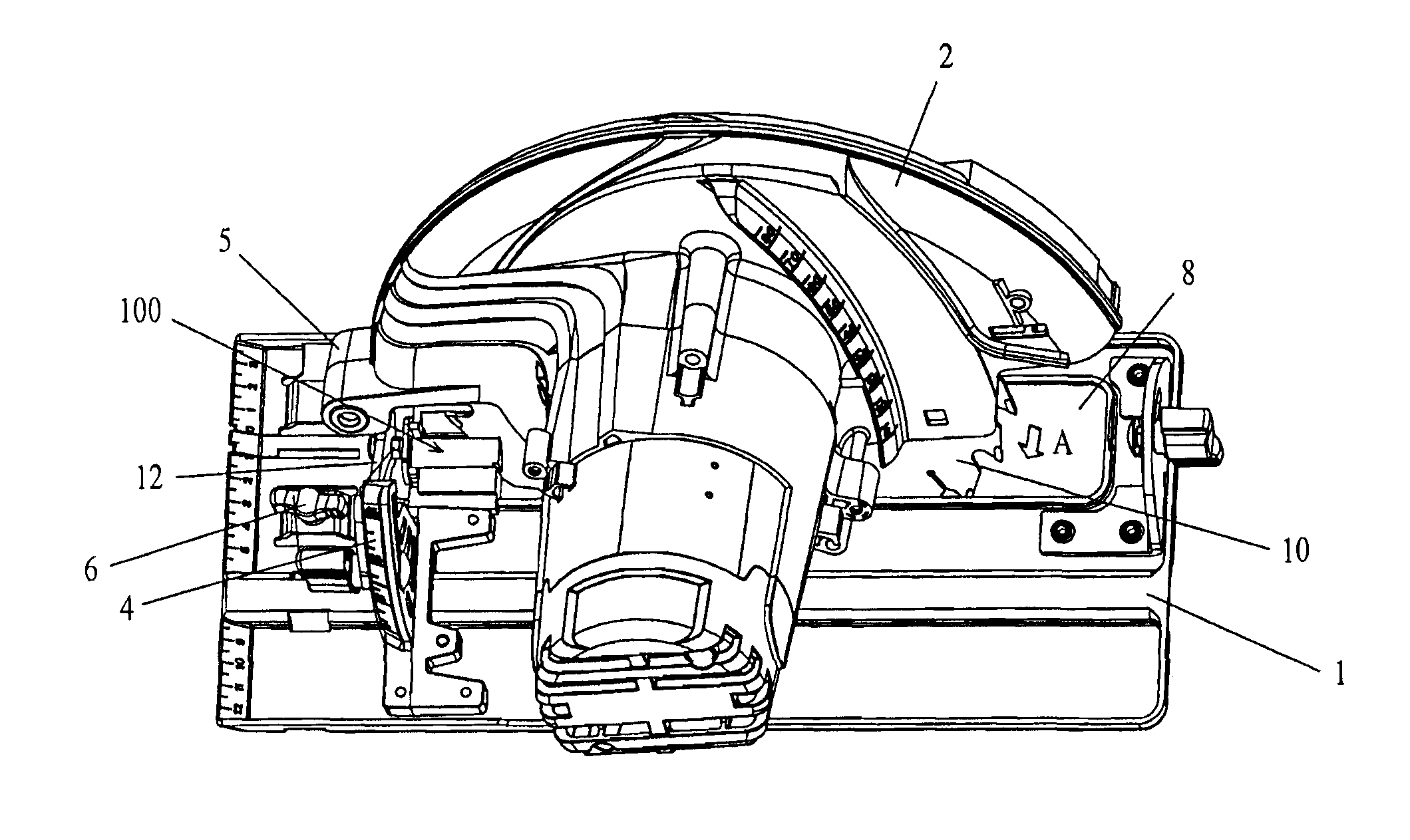
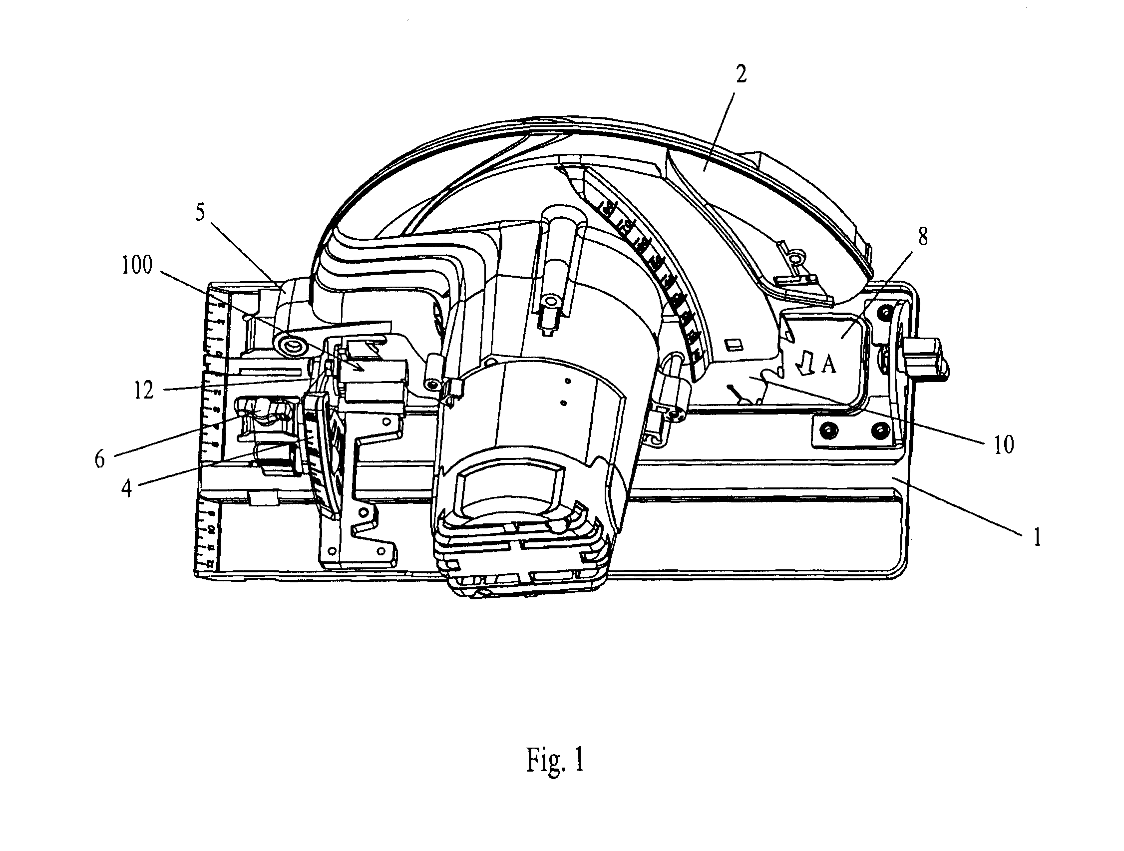
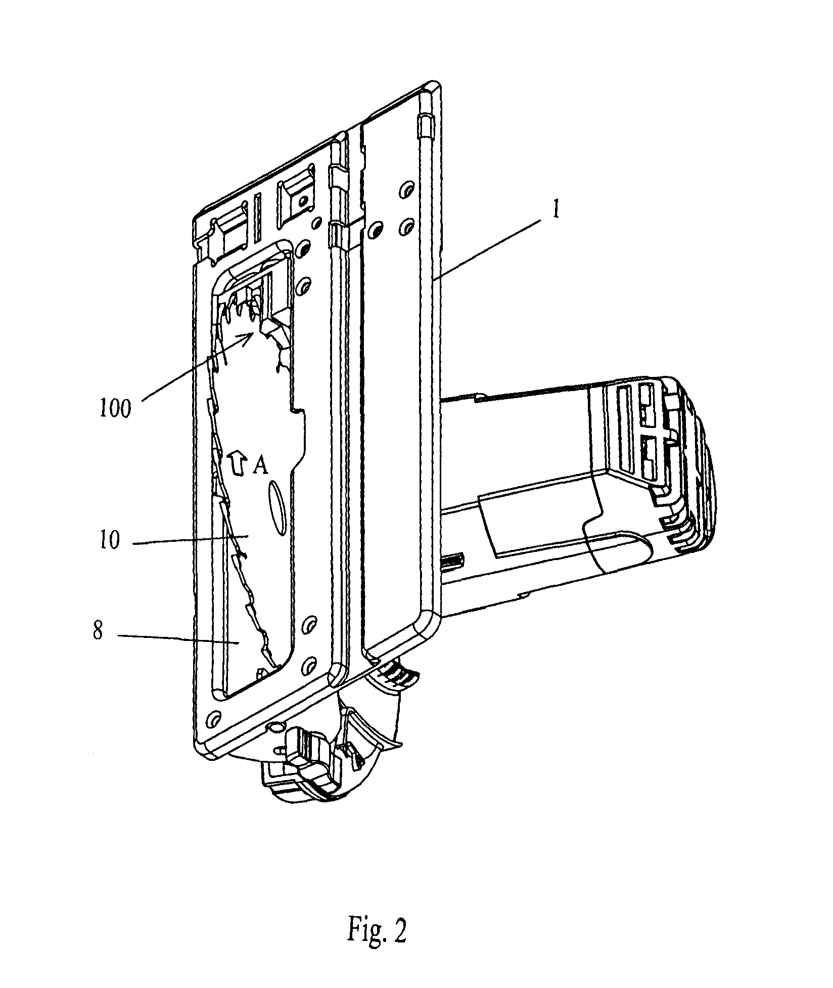
[0028]FIGS. 1 to 3 show a circular saw according to an embodiment of the invention. The circular saw comprises a base plate 1 which has a generally flat shape and thus defines a base plane. The base plate 1 will be put on a surface of the workpiece to perform a cutting operation. A bevel bracket 12 is pivotable supported by the base plate 1, and a casing 2 is pivotable supported by the bevel bracket 12 via a pivoting joint 5. The casing 2 carries a rotary motor (not shown) and a circular saw blade 10 driven in rotation by the motor. A outcoming section of the blade 10, which is to be cut into a workpiece, extends through an elongated opening 8 formed in the base plate 1. The pi...


PUM

PropertyMeasurementUnit
Distanceaaaaaaaaaa
Velocityaaaaaaaaaa

Abstract

A circular saw includes a base plate defining a base plane, a bevel bracket which supports a circular saw blade and is pivotally mounted on the base plate for tilting the blade, the bevel bracket having a pivoting axis which is parallel to the base plane and the blade and perpendicular to a rotational axis of the blade, and the blade partly extending through an opening forming in the base plate, and an anti-splinter device for preventing cutting chips from splintering. The anti-splinter device comprises a pair of slides mounted in the opening and forming a gap between their opposing ends, an outcoming section of the blade passing through the gap, and slide driving means associated with the bevel bracket and driving the slides to move in conformity with the tilting of the blade to allow the gap to accommodate the positional change of the outcoming section of the blade.

Description

TECHNICAL FIELD [0001]The present invention relates to a circular saw with an improved anti-splinter device for preventing chip splintering during the operation of the saw.BACKGROUND ART [0002]Chip splintering happens during the operation of a circular saw. While the saw blade cuts into a workpiece, chips of the workpiece will be engaged by the saw blade and splinter out from the workpiece. Due to the rotation direction of the saw blade, the splintered chips will fly to the operator and sometimes may hurt the operator.[0003]Currently, there are a few structures in the market for preventing chip splintering on the circular saw. One solution is a fixed anti-splinter structure which forms a gap through which the saw blade passes through. The gap is narrow for preventing the chips from splashing between the saw blade and the anti-splinter structure. This anti-splinter structure is effective for straight cutting operation where the saw blade is in a normal vertical orientation. However, ...

Claims


Application Information

Patent Timeline
IPC IPC(8): B27G19/04B27B9/02B23D45/16
CPCB27G19/10B27B9/04
Inventor ZHEN, BOWANG, AIGUI
Owner BOSCH POWER TOOLS CHINA
Learn More