Valve timing control apparatus

Active Publication Date: 2011-10-20
AISIN SEIKI KK
View PDF1 Cites 15 Cited by
  • Summary
  • Abstract
  • Description
  • Claims
  • Application Information

AI Technical Summary

Benefits of technology

[0011]On the other hand, with the technique of Patent Document 2, the angle advancement restricting mechanism and the angle retardation restricting mechanism are provided in close vicinity with each other. However, since the restricting member of the angle advancement restricting mechanism acts both as a component for restraining the relative rotational phase and as a component for restricting it within a predetermined range, upon release of the restraint, this releases the restriction also. Therefore, it is not possible to effect such controlling operation for restr

Problems solved by technology

However, with the technique of Patent Document 1, since the locking mechanism and the restricting mechanism are provided at different positions, the technique tends to invite increase in the complexity of the construction, increase in the number of components and increase in the manufacture cost.
Further, since the locking mechanism and the restricting mechanism are both provided along the direction of relative rotation, the space a

Method used


Image

  • Valve timing control apparatus
  • Valve timing control apparatus
  • Valve timing control apparatus

Examples


Example

MODES OF EMBODYING THE INVENTION

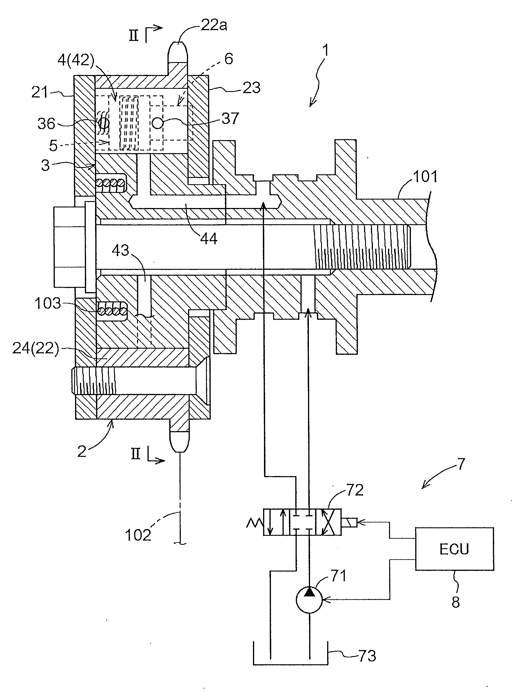
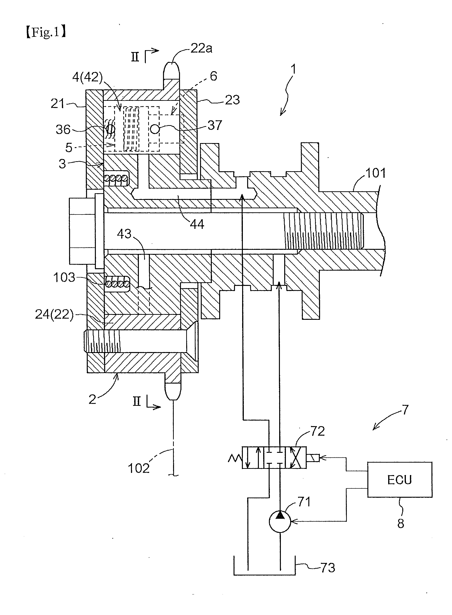
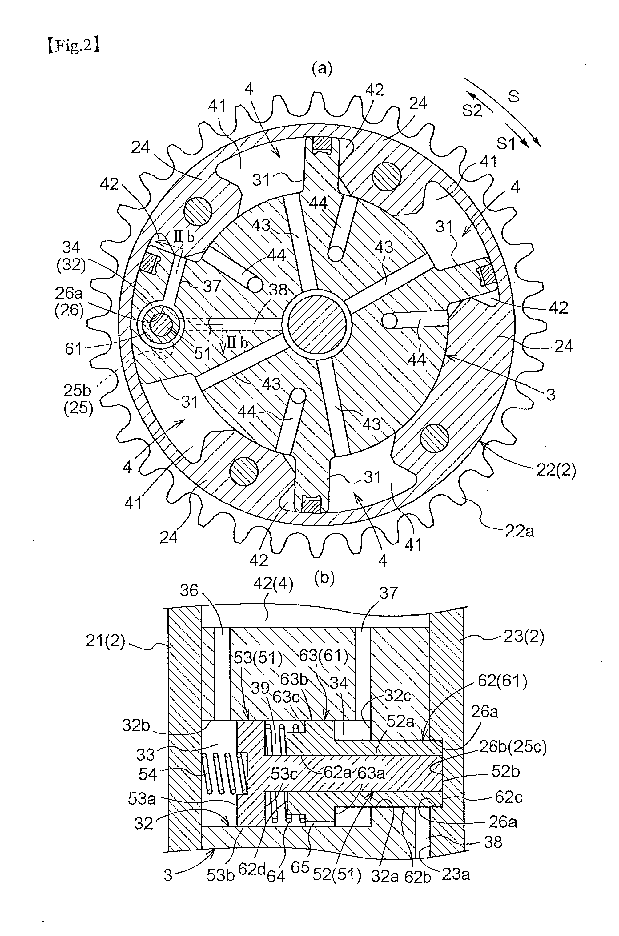
[0070]Now, with reference to FIGS. 1 through 7, a valve timing control apparatus relating to the present invention will be described by way of an embodiment wherein the apparatus is applied as an exhaust-valve side, valve timing control apparatus in an automobile engine. FIG. 2 (b) shows a developed section along direction IIb-IIb in FIG. 2 (a). Unlike IIb-IIb shown in FIG. 2, FIGS. 3 through 6 do not indicate the development direction, but the development directions of the respective figures (b) thereof are same as that of FIG. 2.

[0071][General Construction]

[0072]This valve timing control apparatus 1, as shown in FIG. 1, includes a housing 2 as a “drive-side rotor” rotatable in synchronism with an unillustrated crankshaft of an engine and an inner rotor 3 disposed coaxial relative to the housing 2 and acting as a “driven-side rotor” rotatable in synchronism with a cam shaft 101. The cam shaft 101 is a rotary shaft of an unillustrated cam which contro...


PUM


Abstract

A valve timing control apparatus includes a locking mechanism having a locking member disposed in an accommodating portion formed in one of a drive-side rotor and a driven-side rotor and projectable into and retractable from the other rotor than the one rotor having the accommodating portion and a locking groove defined in the other rotor for receiving and retaining the locking member projecting therein, the locking mechanism for restraining a relative rotational phase when the locking member is retained within the locking groove. The apparatus further includes a restricting mechanism having a restricting member disposed within the accommodating portion and projectable into and retractable from the other rotor to be movable relative to and together with the locking member in a projecting/retracting direction of the locking member and a restricting groove defined in the form of an elongate slot in the other rotor for receiving the restricting member projecting therein, the restricting mechanism restricting the relative rotational phase within a predetermined range when the restricting member projects into the restricting groove.

Description

TECHNICAL FIELD[0001]The present invention relates to a valve timing control apparatus for controlling a relative rotational phase of a driven-side rotor relative to a drive-side rotor which is rotatable in synchronism with a crankshaft of an internal combustion engine.BACKGROUND ART[0002]Conventionally, as disclosed in Patent Document 1 identified below, there was known a valve timing control apparatus including a locking mechanism for restraining a relative rotational phase of a driven-side rotor relative to a drive-side rotor and a restricting mechanism provided at a different position along the direction of relative rotation than the locking mechanism and configured for restricting a relative rotational movement within a predetermined range. The locking mechanism includes a locking member provided in the drive-side rotor and a locking groove defined in the driven-side rotor for receiving and retaining the locking member projecting therein. Further, the restricting mechanism incl...

Claims


Application Information

Patent Timeline
IPC IPC(8): F01L1/344
CPCF01L1/3442F01L2001/34426F01L2250/02F01L2001/34476F01L2001/34479F01L2001/34469
Inventor IKEDA, KENJI
Owner AISIN SEIKI KK
Why Eureka
Try Eureka