Method and device for removing biological nitrogen and support therefor

a biological nitrogen and removal method technology, applied in the direction of moving filter element filters, water treatment parameter control, water/sludge/sewage treatment, etc., can solve the problems of high equipment cost of biological nitrogen removal devices, and inability to achieve simple methods, etc., to achieve the effect of suppressing the nitrate type nitrification reaction

Active Publication Date: 2011-10-20
METAWATER CO LTD
View PDF1 Cites 24 Cited by
  • Summary
  • Abstract
  • Description
  • Claims
  • Application Information

AI Technical Summary

Benefits of technology

[0042]As described above, acceleration of a nitrite type nitrification reaction and suppression of a nitrate type nitrification reaction have been achieved respectively by controlling the ammonia nitrogen concentration of water to be treated, which is a target of the treatment, and the water temperature, DO value, and pH value in the reaction tank. In the present invention, on the other hand, in order to simultaneously achieve acceleration of a nitrite type nitrification reaction and suppression of a nitrate type nitrification reaction by making use of the fact that formation of nitrous acid contributes to the inhibition of a nitrate type nitrification reaction, acceleration of the nitrite type nitrification reaction is performed at such a level as to suppress the nitrate type nitrification reaction. This makes it possible to carry out denitrification in a practical level by making use of an anaerobic ammonia oxidation reaction while relaxing the limitations on the ammonia nitrogen concentration in the water to be treated, which is a target of the treatment, and the water temperature, DO value, and pH value in the reaction tank.

Problems solved by technology

Such a biological nitrogen removal technology requires a large amount of oxygen in the nitrification step, while a large amount of an organic matter such as methanol should be added in the denitrification step, which totally increases a running cost.
In such a biological nitrogen removal method and a biological nitrogen removal device, the partial nitritation tank, the pH regulating tank, and the denitrification tank should be provided separately and the pH in the nitritation tank and the denitrification tank should be adjusted to a pH value necessary for the partial nitritation reaction and the denitrification reaction, respectively, so that the device needs a high equipment cost as a biological nitrogen removal device and the method is not simple as a biological nitrogen removal method.
This biological nitrogen removal method making use of the anaerobic ammonia oxidation reaction however has the following technological problem.
Thus, it is difficult to say that denitrification of water to be treated containing ammonia nitrogen can be performed at a practical level under any conditions by using an anaerobic ammonia oxidation reaction.
Since municipal wastewater or domestic wastewater has a lower temperature and a lower ammonia nitrogen concentration, it is difficult to apply the method to the treatment of such wastewater as is.

Method used


Image

  • Method and device for removing biological nitrogen and support therefor
  • Method and device for removing biological nitrogen and support therefor
  • Method and device for removing biological nitrogen and support therefor

Examples


example 1

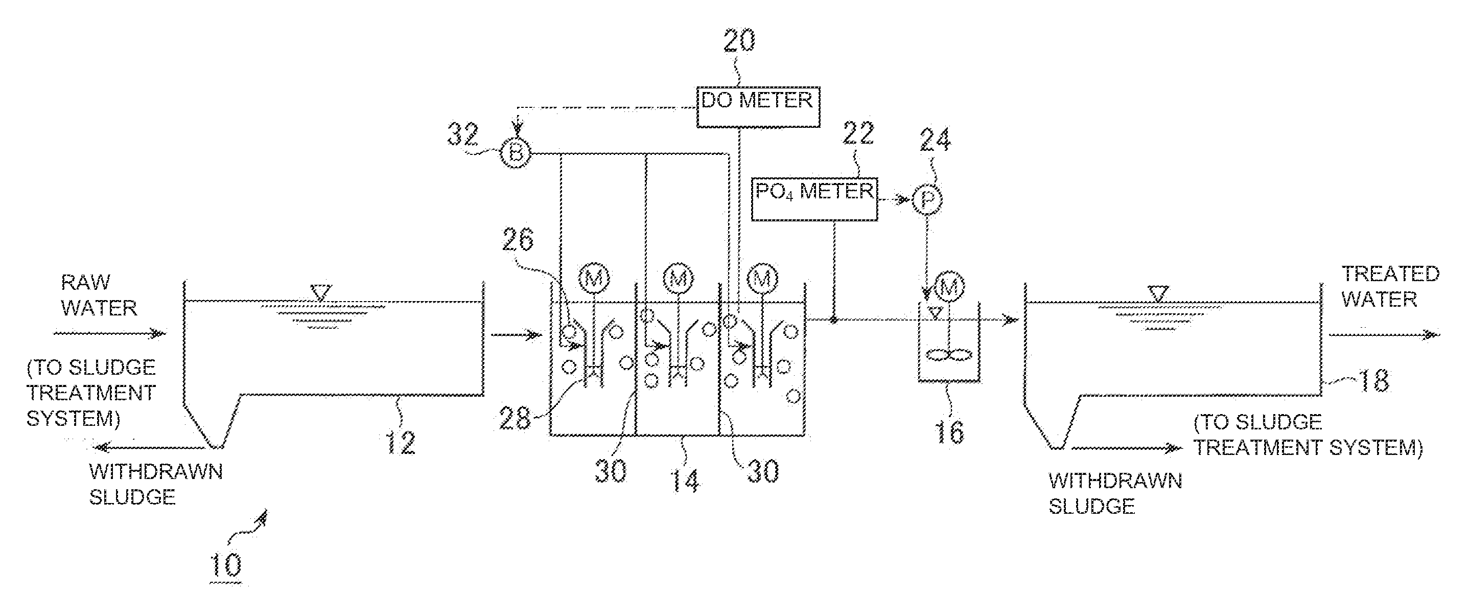
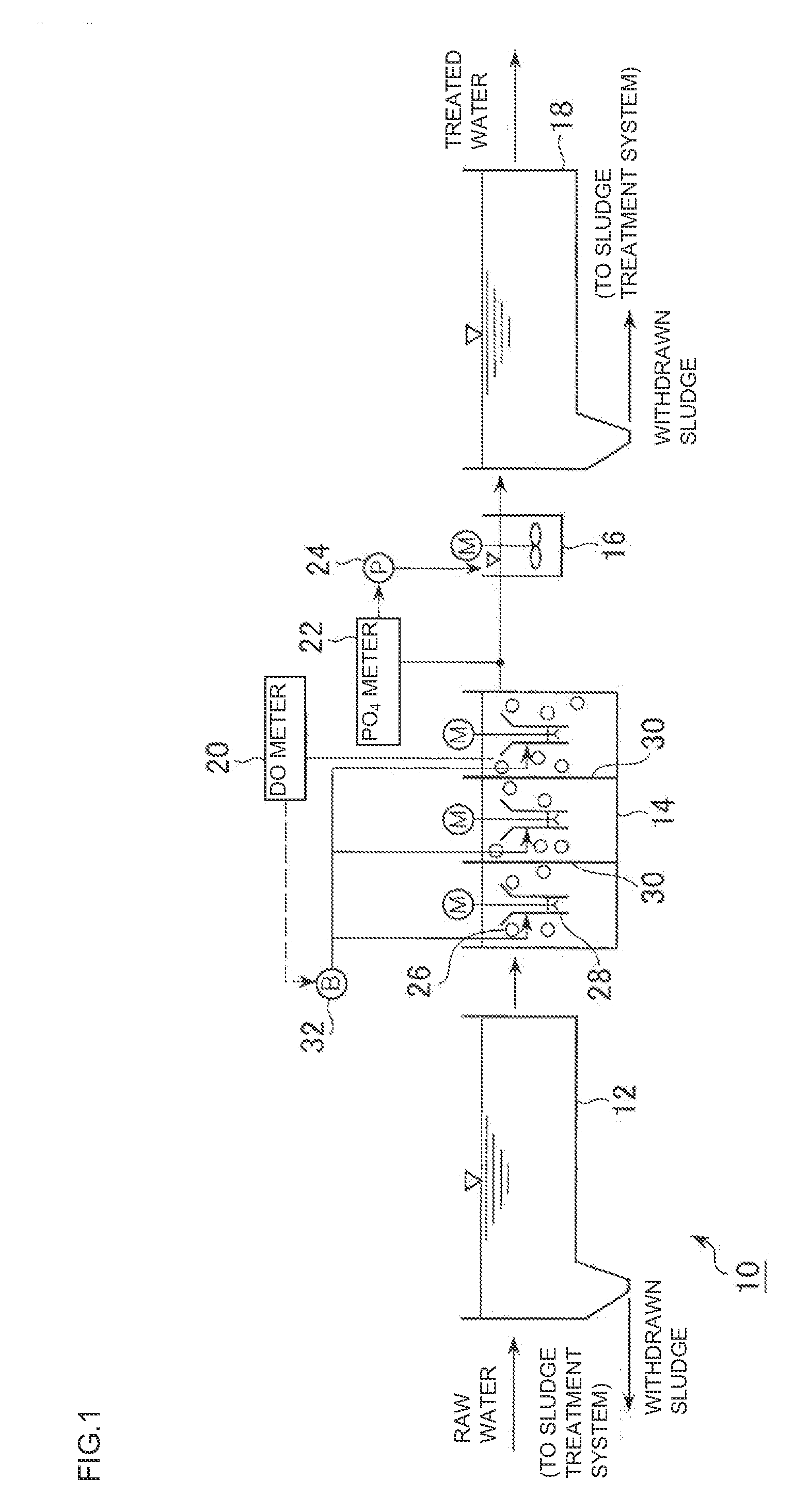
[0101]The present inventors made a test on normal sewage at a practical level by using the reaction tank 14 described in the above embodiment. As a result, it has been confirmed that when stirring a support having, on the surface portion thereof, nitrite type nitrifying bacteria and anaerobic ammonia oxidizing bacteria in the sewage, which is water to be treated, while diffusing air into the sewage by using a draft tube aerator, it is possible to secure a denitrification efficiency of a practical level while relaxing limitations on the ammonia nitrogen concentration in water to be treated and water temperature, DO value, and pH value in the reaction tank by adjusting a feed rate of support. The term “denitrification efficiency” as used herein means a nitrogen removal amount per unit reaction capacity per unit hour.

[0102]Table 1 shows comparison between operation conditions employed here (operation conditions in examples of the present invention) and operation conditions disclosed in...

example 2

[0107]In order to confirm the influence of the feed rate of support on the nitrogen removal rate, the present inventor made a test (batch test) as described below by taking out a small amount of a support used for the continuous operation in Example 1 and charging it in a beaker containing sewage of an actual sewage plant as water to be treated. The test was made under the following conditions.

[0108](Common Conditions)

[0109](1) Bacteria: nitrite type nitrifying bacteria and anaerobic ammonia oxidizing bacteria

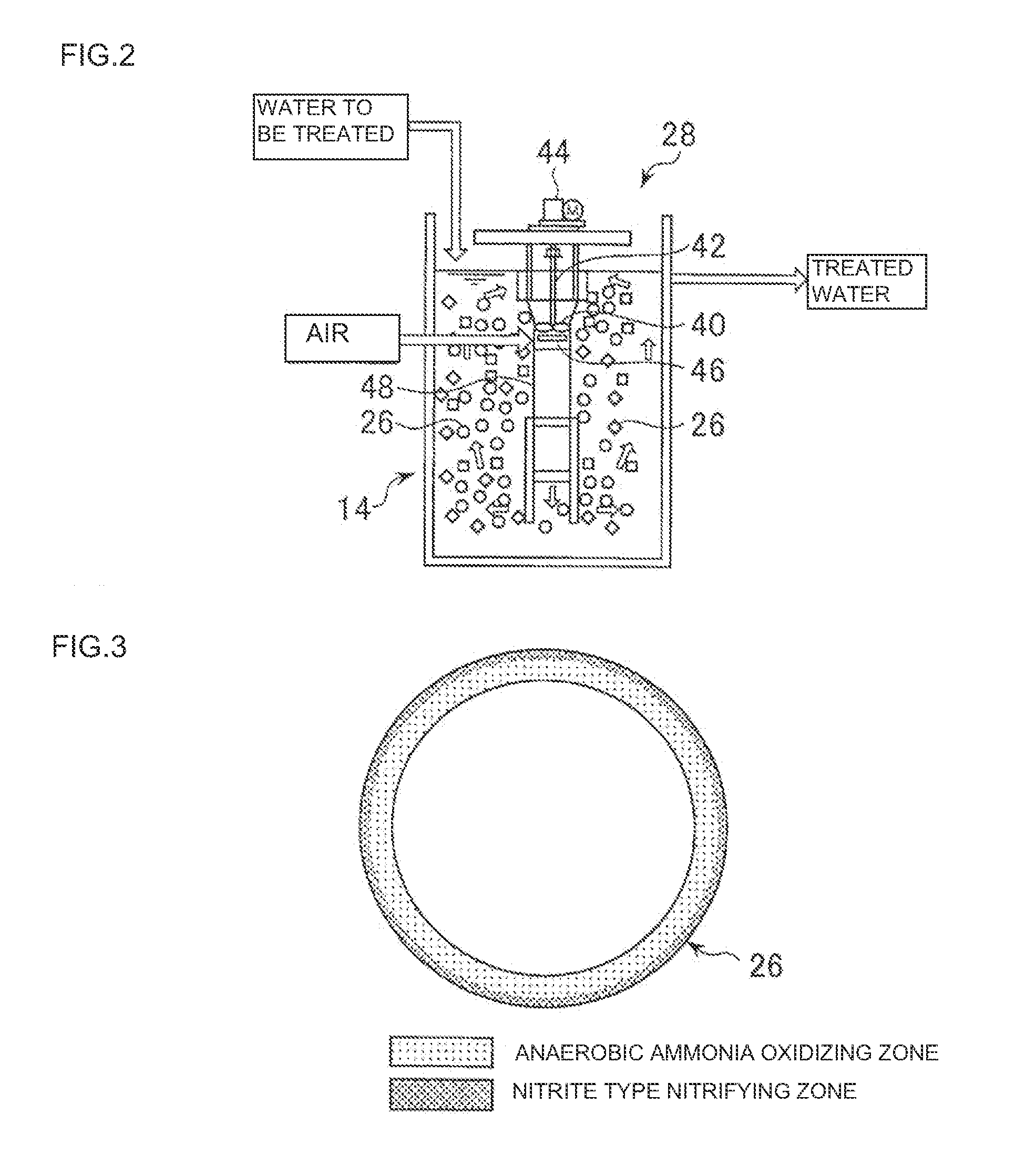
[0110](2) Bacteria supporting method: a two-layered microbial film having, in the outer layer thereof, nitrite type nitrifying bacteria as a dominant species and in the inner layer, anaerobic ammonia oxidation dye as a dominant species while being surrounded with the nitrite type nitrifying bacteria is supported on a columnar support (4.0 mm diameter×4.3 mm length) made of a polyurethane resin.

[0111](3) Water to be treated: a supernatant obtained by precipitating a mixture in a...


PUM

PropertyMeasurementUnit
oxidation reduction potentialaaaaaaaaaa
concentrationaaaaaaaaaa
feed rateaaaaaaaaaa

Abstract

Provided is a biological nitrogen removal method which includes, causing to flow a support having, on the surface portion thereof, a two-layered microbial film which holes, in the outer layer, nitrite type nitrifying bacteria or aerobic bacteria and nitrite type nitrifying bacteria as a dominant species and, in the inner layer, anaerobic ammonia oxidizing bacteria as a dominant species while being surrounded with the nitrite type nitrifying bacteria; and thereby carrying out denitrification of the water to be treated by making use of the anaerobic ammonia oxidation reaction. In the biological nitrogen removal method, a feed rate of the support (total surface area of the support per unit capacity of the reaction tank) is adjusted so that an amount of nitrous acid produced by the nitrite type nitrification reaction through the action of the nitrite type nitrifying bacteria reaches a level to inhibit a nitrate type nitrification reaction.

Description

TECHNICAL FIELD[0001]The present invention relates to a biological nitrogen removal method and nitrogen removal device making use of an anaerobic ammonia oxidation reaction, with water to be treated containing a soluble nitrogen such as ammonia nitrogen as a target; a water treatment system equipped with the nitrogen removal device; and a support having thereon bacteria and utilized in the biological nitrogen removal method and the nitrogen removal device. More specifically, the invention relates to a biological nitrogen removal method and nitrogen removal device capable of carrying out denitrification at a practical level while relaxing limitations on an ammonia nitrogen concentration in water to be treated, which is the target of the treatment, and a water temperature, a DO value, and a pH value in a reaction tank; a water treatment system equipped with the nitrogen removal device; and a support having thereon bacteria and utilized in the biological nitrogen removal method and the...

Claims


Application Information

Patent Timeline
Patent Type & Authority Applications(United States)
IPC IPC(8): C02F3/30C12N1/20
CPCC02F3/006C02F3/087C02F3/109C02F3/302C02F3/341C02F3/348C02F2209/22C02F2209/04C02F2209/06C02F2209/15C02F2209/16C02F2209/18C02F2209/02Y02W10/10C02F3/10C02F3/2813C02F3/305
Inventor TAKEDA, SHIGEKI
Owner METAWATER CO LTD
Why Eureka
Try Eureka