Wireless IC devICe, wireless IC module and method of manufacturing wireless IC module
- Summary
- Abstract
- Description
- Claims
- Application Information
AI Technical Summary
Benefits of technology
Problems solved by technology
Method used
Image

Examples
first preferred embodiment
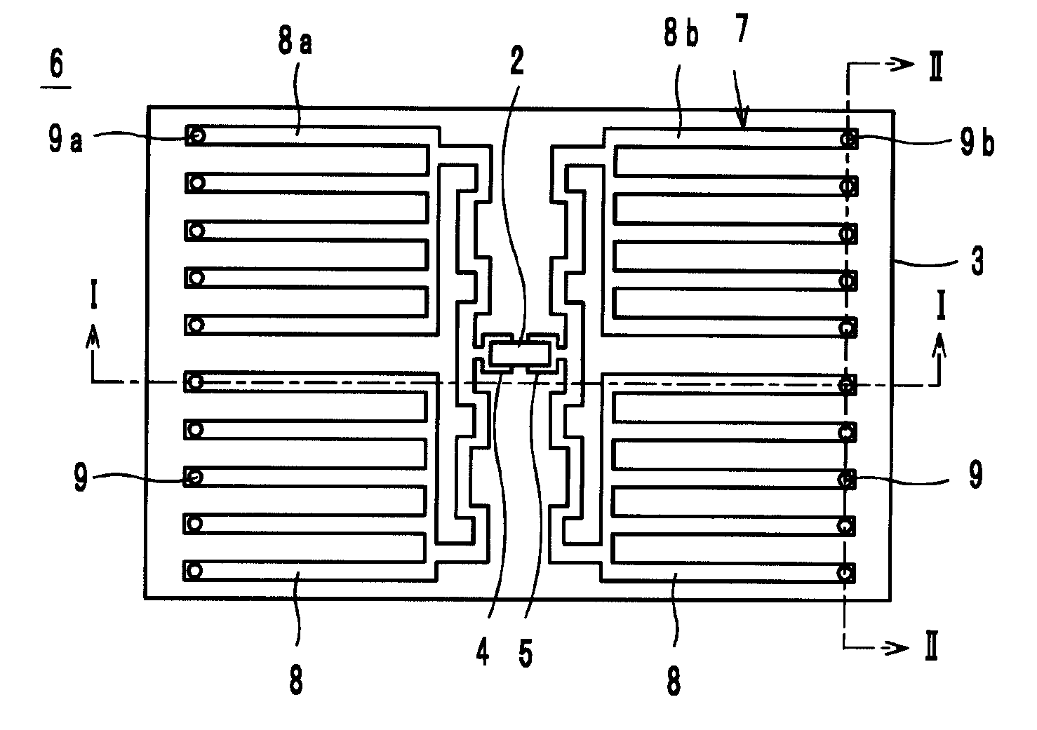
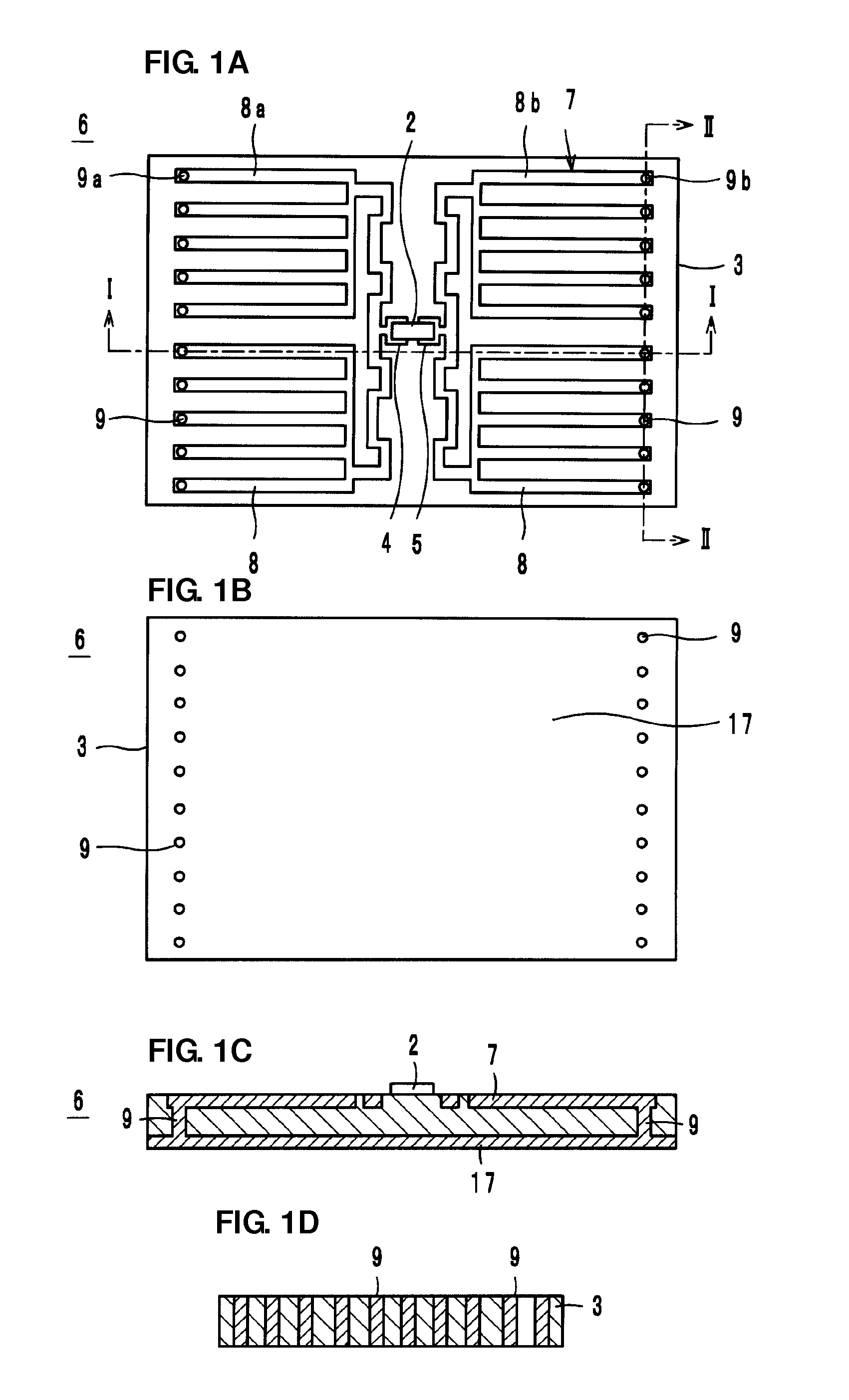
[0038]FIGS. 1A-1D illustrate a wireless IC module 6 according to a first preferred embodiment, where FIG. 1A is a plan view, FIG. 1B is a bottom surface view, FIG. 1C is a sectional view taken along line I-I of FIG. 1A, and FIG. 1D is a sectional view taken along line II-II of FIG. 1A.
[0039]A wireless IC module 6 includes a wireless IC 2 that processes predetermined radio signals and loop-shaped electrodes 7. The wireless IC 2 is disposed on two-end coupling portions 4 and 5 of the loop-shaped electrodes 7, and the wireless IC 2 and the loop-shaped electrodes 7 are electromagnetically coupled with each other. The wireless IC 2 and the loop-shaped electrodes 7 may instead be directly electrically connected with each other (DC connection).
[0040]The loop-shaped electrodes 7, include electrodes, that is, the two-end coupling portions 4 and 5 and line-shaped electrodes 8 located on a board 3, via hole conductors 9 formed through the board 3 and a common electrode 17 located on the bottom...
second preferred embodiment
[0064]FIGS. 7A-7C illustrates a wireless IC module 66 according to a second preferred embodiment, where FIG. 7A is plan view, FIG. 7B is a bottom surface view and FIG. 7C is a sectional view taken along line III-III of FIG. 7A.
[0065]The wireless IC module 66 according to the second preferred embodiment, similarly to as in the first preferred embodiment, includes a wireless IC 22, two-end coupling portions 24 and 25, a plurality of line-shaped electrodes 28 and via hole conductors 29. The two-end coupling portions 24 and 25, the plurality of line-shaped electrodes 28 and the via hole conductors 29 are formed on and through a board 23. However, in contrast to the first preferred embodiment, the wireless IC module 66 does not have a common electrode on the back surface of the board 23, which is the mounting surface thereof. Therefore, the two-end coupling portions 24 and 25, the plurality of line-shaped electrodes 28 and the via hole conductors 29 define loop-shaped electrode portions ...
third preferred embodiment
[0069]FIGS. 10A-10C illustrates a wireless IC module 600 according to a third preferred embodiment, where FIG. 10A is a plan view, FIG. 10B is a bottom surface view and FIG. 10C is a side surface view.
[0070]The wireless IC module 600 according to the third preferred embodiment, similarly to as in the first preferred embodiment, includes a wireless IC 200, two-end coupling portions 400 and 500, a plurality of line-shaped electrodes 800 and a common electrode 170, but in contrast to in the first preferred embodiment the components are covered by a polyethylene terephthalate (PET) film 303 and therefore are indicated using dashed lines. Furthermore, the wireless IC module 600 does not include via hole conductors. Accordingly, the line-shaped electrodes 800 are connected to the common electrode 170 along side surfaces of a board 300. In other words, loop-shaped electrodes 700 include the two-end coupling portions 400 and 500, the line-shaped electrodes 800 and the common electrode 170, ...
PUM
 Abstract
Description
Claims
Application Information
 - R&D Engineer
- R&D Manager
- IP Professional
- Industry Leading Data Capabilities
- Powerful AI technology
- Patent DNA Extraction
Browse by: Latest US Patents, China's latest patents, Technical Efficacy Thesaurus, Application Domain, Technology Topic.
© 2024 PatSnap. All rights reserved.Legal|Privacy policy|Modern Slavery Act Transparency Statement|Sitemap