Portable wireless device

Inactive Publication Date: 2011-05-05
PANASONIC CORP
View PDF5 Cites 3 Cited by
  • Summary
  • Abstract
  • Description
  • Claims
  • Application Information

AI Technical Summary

Benefits of technology

[0027]In the portable radio of the present invention, the first hinge acts as the ground in the first dipole antenna and acts also as the power feed system in the second dipole antenna for feeding electric power from the second circuit board to the first circuit board. As a result, two dipole antennas having different polarized waves are realized, and the portable radio can exhibit high communication performance appropriate for its operating state despite its small size and low profile.

Problems solved by technology

However, in the foldable portable phone shown in FIG. 10, an electric current flowing through the lower enclosure is large; hence, gain deterioration which arises when the mobile phone is used while gripped by hand is large.

Method used


Image

  • Portable wireless device
  • Portable wireless device
  • Portable wireless device

Examples


first embodiment

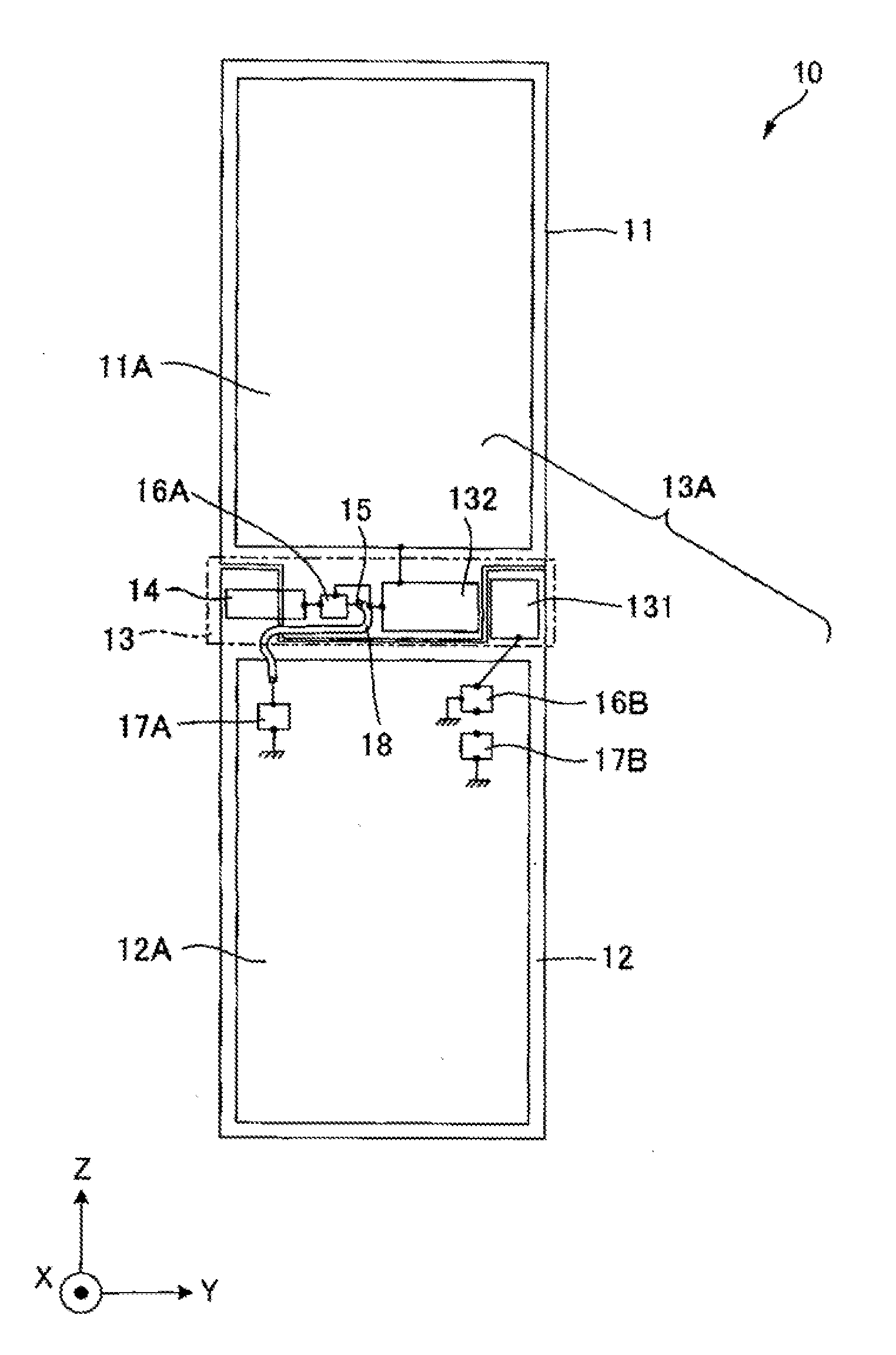
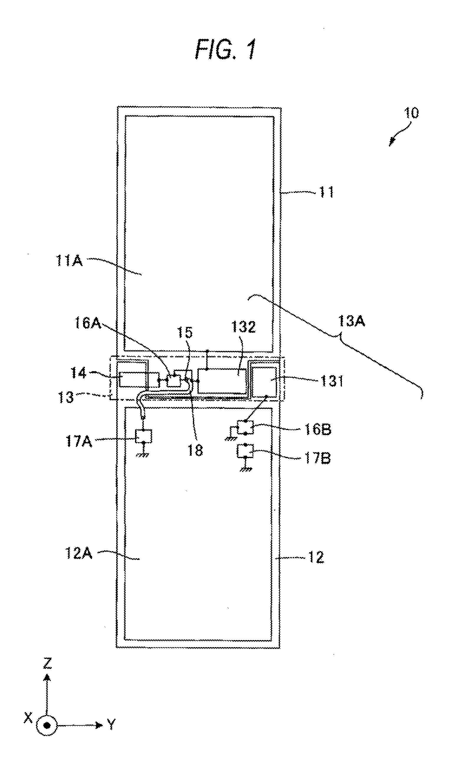
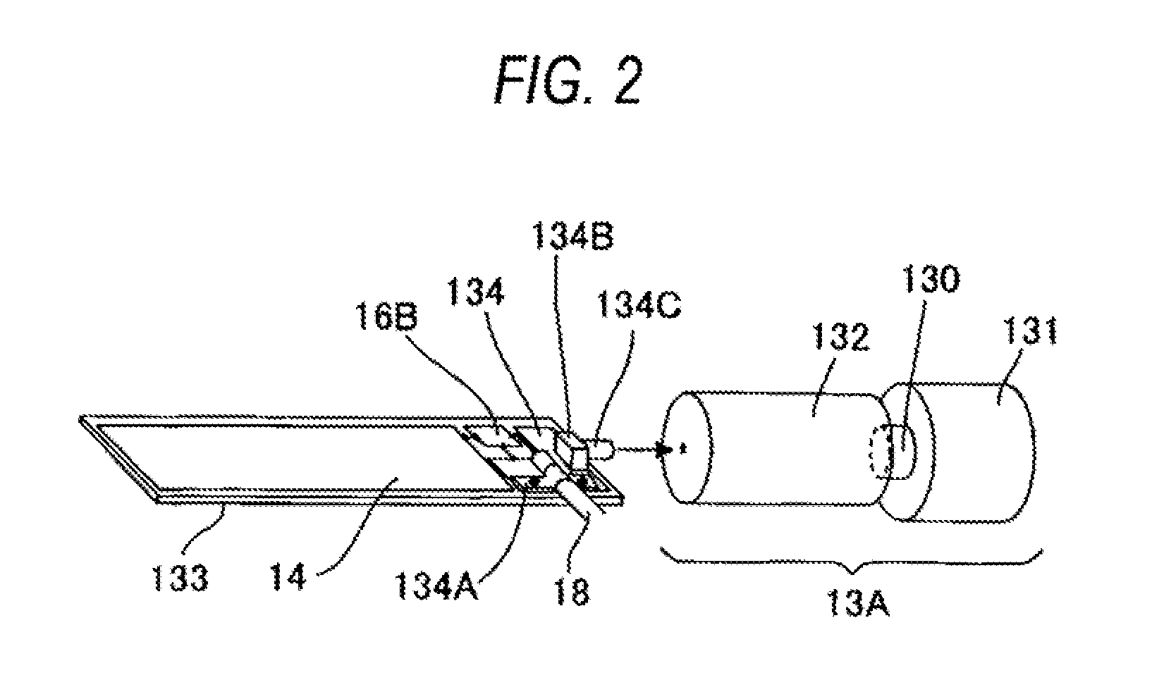
[0064]FIG. 1 shows a foldable portable phone 10 of a first embodiment of a portable radio of the present invention. The foldable portable phone 10 has an upper enclosure 11 making up a first enclosure; a lower enclosure 12 making up a second enclosure; a hinge 13 that joins the upper enclosure 11 to the lower enclosure 12 in a rotatable manner; an antenna element 14; a first impedance matching circuit 16A and a second impedance matching circuit 16B; a first radio circuit 17A and a second radio circuit 17B; and a coaxial line 18.

[0065]The upper enclosure 11 has an un-illustrated display unit and a first circuit board (an upper circuit board) 11A. The lower enclosure 12 has an un-illustrated operation unit, a second circuit board (a lower circuit board) 12A, the foregoing second impedance matching circuit 16B, the foregoing first radio circuit 17A, and the foregoing second radio circuit 17B.

[0066]The hinge 13 has a hinge element 13A making up a first hinge, the foregoing antenna eleme...

second embodiment

[0088]A second embodiment of the present invention is now described in detail by reference to FIG. 4. In the present embodiment, elements that are the same as those described in connection with the first embodiment are assigned the same reference numerals, and their repeated explanations are omitted here for brevity.

[0089]In addition to including the upper enclosure 11, the lower enclosure 12, the hinge 13, the antenna element 14, the first impedance matching circuit 16A, the second impedance matching circuit 16B, the first radio circuit 17A, the second radio circuit 17B, and the coaxial line 18, a foldable portable phone 20 of the present embodiment includes a first filter 21A, a second filter 21B, and a third filter 21C.

[0090]When the first dipole antenna made up of the antenna element 14 and the hinge element 13A of the first embodiment operates at the frequency f1 (a first frequency), the hinge element 13A is shared by a power feed system of the frequency f2 (a second frequency)...

third embodiment

[0095]A third embodiment of the present invention is described in detail by reference to FIG. 5. In the present embodiment, elements that are the same as those described in connection with the first embodiment are assigned the same reference numerals, and their repeated explanations are omitted here for brevity.

[0096]Unlike the foldable portable phone of the first embodiment, a foldable portable phone 30 of the present embodiment has a single radio circuit 31 in place of the first radio circuit 17A and the second radio circuit 17B. The portable phone also has a high frequency switch 32 for switching circuitry between the radio circuit 31 and the first impedance matching circuit 16A, the second impedance matching circuit 16B.

[0097]The radio circuit 31 switches the circuitry by means of the high frequency switch 32, thereby doubling as radio circuits for the second dipole antenna and the first dipole antenna. The second dipole antenna and the first dipole antenna are structurally iden...


PUM


Abstract

There is provided a foldable portable radio that can exhibit high phone call performance despite its low profile and small size.An antenna element 14 to be placed in the vicinity of a first hinge element 13A is connected to a power feed unit. The first hinge element 13A has a hinge fixing unit 131 and a hinge rotating unit 132. The hinge fixing unit 131 is connected to a second radio circuit 17B of a lower circuit board 12A by way of a second matching circuit 16B. The hinge rotating unit 132 is placed while spaced apart from a ground pattern on an upper circuit board 11A by a predetermined interval and connected to an end of the ground pattern of the upper circuit board that is close to the first hinge element 13A. The antenna element 14 and the first hinge element 13A configure a first dipole antenna. The ground pattern of the upper circuit board 11A and a ground pattern of the lower circuit board 12A configure a second dipole antenna that takes the hinge element 13A as a power feed system. The first hinge element 13A acts as a ground in the first dipole antenna and also as a power feed system in the second dipole antenna.

Description

TECHNICAL FIELD[0001]The present invention relates to a slim, foldable, portable radio that exhibits high phone call performance and that is compatible with a plurality of radio systems.BACKGROUND ART[0002]Various portable radios such as portable phones, have hitherto been developed. In relation to the portable phones, various types of fordable portable phones each of which can perform re-closable round a hinge unit have been developed. In such a foldable portable phone, a display unit is placed in an upper enclosure. Due to limitations on space, a radio circuit is placed in a lower enclosure in many times. Further, in order to minimize a pass loss occurring between the radio circuit and an antenna, it is preferable to place the antenna in the vicinity of the radio circuit. Accordingly, in order to suppress the pass loss occurring between the radio circuit and the antenna, the antenna is often placed in the vicinity of the hinge unit of the lower enclosure. A known specific example ...

Claims


Application Information

Patent Timeline
IPC IPC(8): H01Q9/28H01Q5/10
CPCH01Q1/243H01Q9/285H04M1/0222H01Q21/28H04M1/0216H01Q21/24
Inventor NISHIKIDO, TOMOAKIUNO, HIROYUKIKOSHI, MASASHIKOYANAGI, YOSHIONAGANO, KENYA
Owner PANASONIC CORP
Why Eureka
Try Eureka