

Mount for a flat panel display
- Summary
- Abstract
- Description
- Claims
- Application Information
AI Technical Summary
Benefits of technology
Problems solved by technology
Method used
Image

Examples
first embodiment
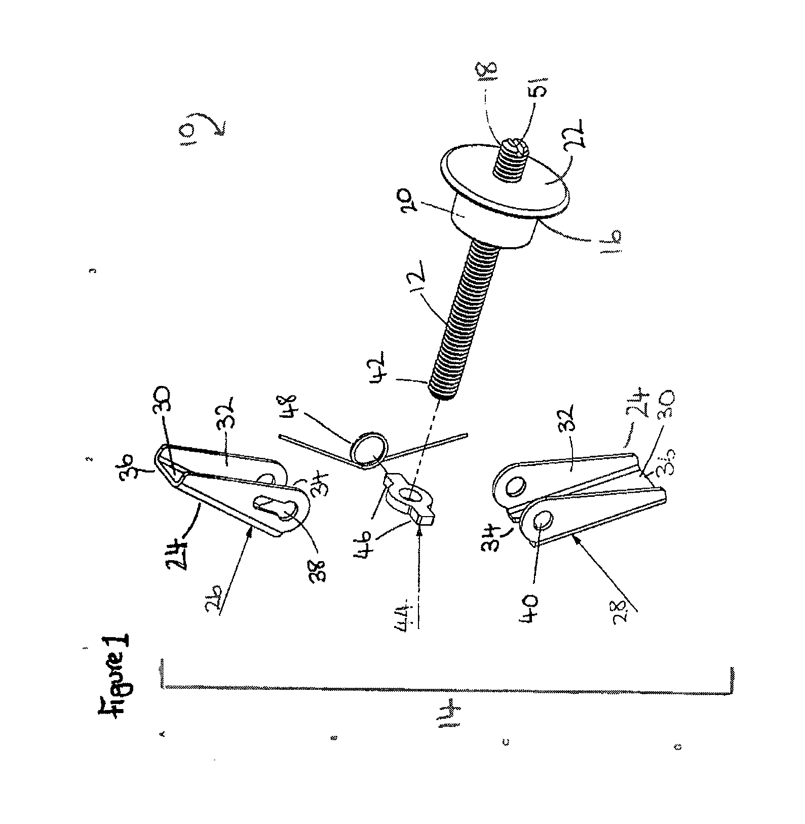
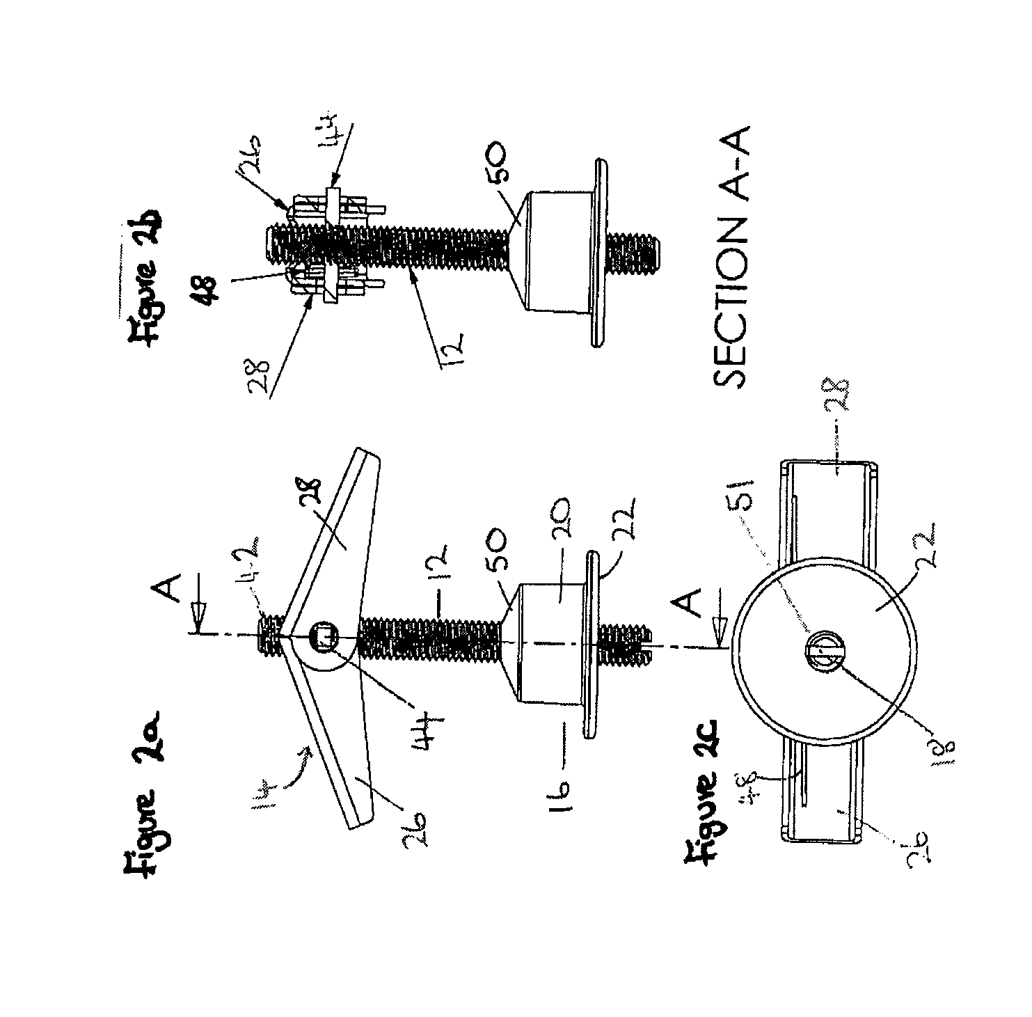
[0096]With reference to FIG. 1, there is illustrated a fixing 10 according to the present invention. The fixing 10 comprises a shaft 12 constituted by a headless screw, an anchor 14 and a plug 16. The plug 16 is immovably mounted on the shaft 12 near to a first end 18 of the shaft 12. The plug comprises a cylindrical body 20 and a disc-shaped head 22 which is of greater diameter than the body 20. The head 22 of the plug 16 is positioned closer to the first end 18 of the shaft 12 than the body 20.
[0097]The anchor 14 comprises a pair of wings 24 comprising an inner wing 26 and an outer wing 28. Each of the wings 26, 28 comprises a substantially flat rectangular panel 30. Along the length of each long side of the rectangular panel 30 a flange 32 is provided. In the embodiment shown, the panel 30 and the flanges 32 are integrally formed from a single piece of material, although in alternative embodiments the flanges may be formed as separate components. The flange 32 is wider at the inn...
second embodiment
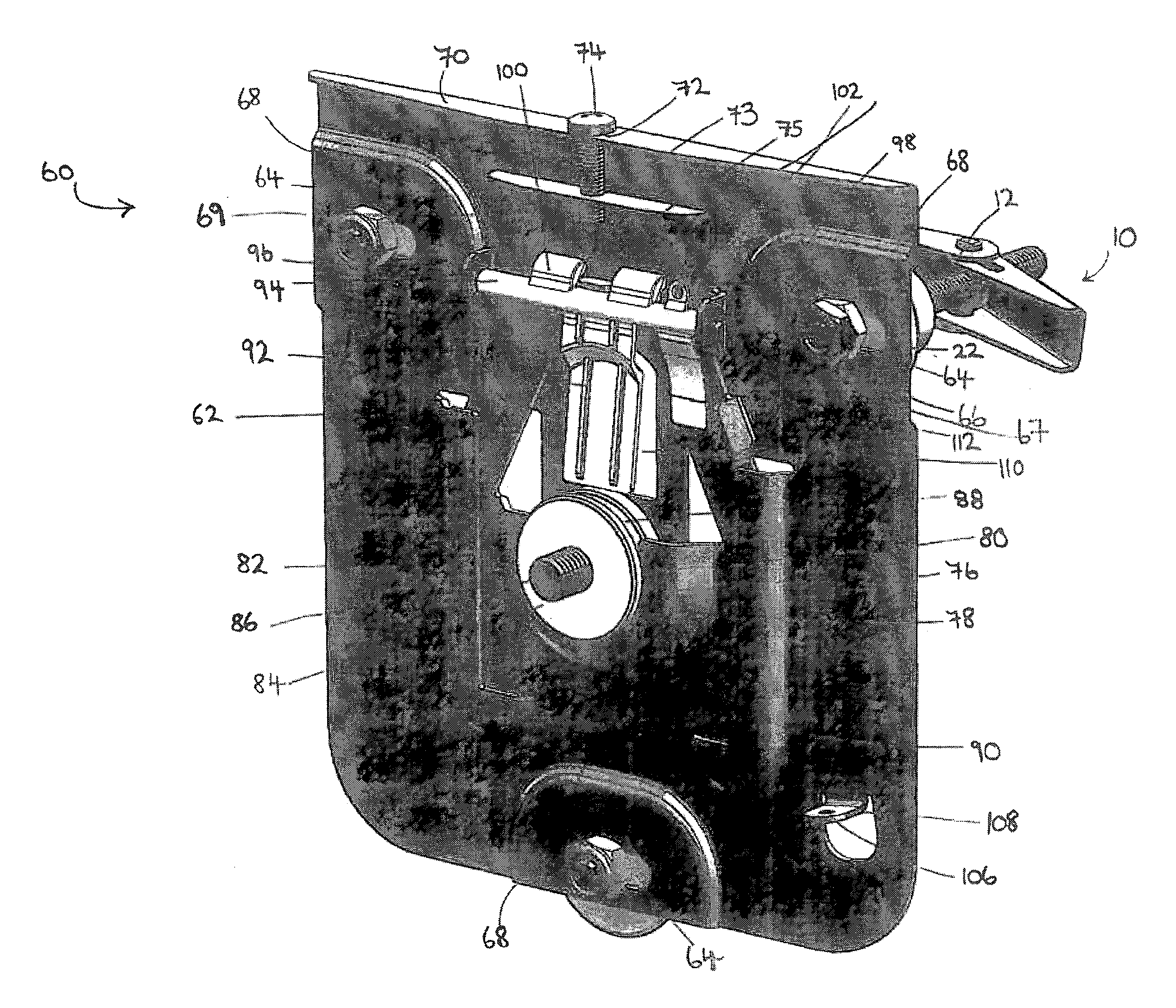
[0103]With reference to FIG. 4, there is illustrated a mount 60 according to the present invention. The mount comprises a first component which includes a substantially flat metal base plate 62. The base plate 62 comprises three horizontal slots 64 in a triangular arrangement. Two of the slots 64 are positioned near to the top and close to the side edges of the base plate 62, and are horizontally aligned. The third slot 64 is positioned centrally close to the bottom edge of the base plate 62, and is equidistant from the other two slots 64. Through each slot 64 passes a shaft 12 of a fixing 10. The base plate 62 is secured onto each shaft 12 by a nut 66 and a locking nut 67. The locking nuts 67 prevent the nuts 66 from coming loose over time. The particular arrangement of slots 64 in the base plate 62 is important to spread the mounted load. However, it will be understood that alternative arrangements and / or an alternative number of fixings may be employed to fix the first component ...
third embodiment
[0112]FIG. 6a shows the present invention in the form of a mount 119 comprising a first component 120, a cover 122 and a boss (not shown). The first component 120 is substantially the same as the first component of the mount 60 shown in FIG. 4, as described above, and the boss (not shown) is identical to the second component of the mount 60. However, in the embodiment of FIG. 6a, a base plate 121 is provided which is curved instead of being rectangular like the base plate 62 shown in FIGS. 4 and 5. The cover 122 comprises three holes 124 in a triangular arrangement which correspond to the positions of the fixings 10 (not shown). A central aperture 126 is also provided in the cover 122 through which the boss 84 is slotted to engage with the socket 82 on the first component 120. The side walls of the holes 124 and aperture 126 are sloped, to help guide components more easily through the holes, and to improve the appearance of the mount 60. A notch 128 is also provided in the cover 122...
PUM
 Abstract
Description
Claims
Application Information