

Fault protected current source for lighting element testing
a current source and lighting element technology, applied in the direction of automatic control, process and machine control, instruments, etc., can solve the problems of failures in a reasonable amount of time, failure rates can still be low, and accelerate the normal aging process of led materials, so as to achieve accurate reliability test data
- Summary
- Abstract
- Description
- Claims
- Application Information
AI Technical Summary
Benefits of technology
Problems solved by technology
Method used
Image

Examples
Embodiment Construction
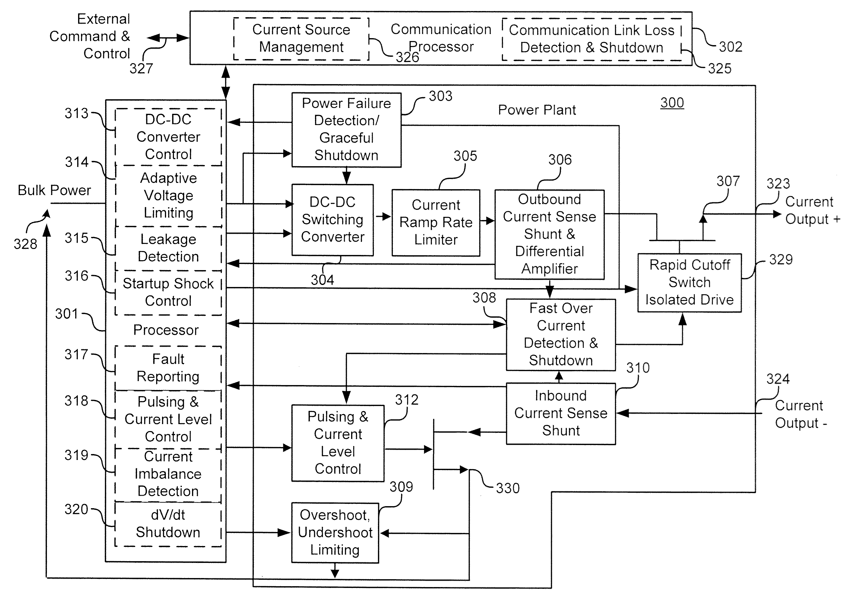
[0012]In various embodiments of the invention, a fault protected current source is provided that can be used to safely drive LEDs in reliability test systems. The current source is includes circuits and processes that detect the common faults found in LED reliability test systems. After a fault is detected, the current source shuts down drive current before destructive spikes are produced. Because only true LED failures are counted, this fault protected current source can be used to construct reliability test systems that produce more accurate reliability test data.
[0013]According to an embodiment of the invention, a fault protected current source, comprises a positive current output and a negative current output, a DC-DC converter configured to adjust a maximum output voltage for the current source in response to a control signal, an over current detection module configured to monitor the current, and a processor configured to monitor voltage, to provide the control signal to the d...
PUM
| Property | Measurement | Unit |
|---|---|---|
| Current | aaaaa | aaaaa |
| Current | aaaaa | aaaaa |
| Electric potential / voltage | aaaaa | aaaaa |
Abstract
Description
Claims
Application Information