
Visual tracking of objects in images, and segmentation of images

a technology for visual tracking and objects, applied in the field of visual tracking of objects in captured digital images, and image segmentation, can solve the problems of difficult to achieve, difficult to predict shape, and difficult to automate tracking targets in images that move from frame to frame, so as to achieve the effect of improving results and being easy to perform

Inactive Publication Date: 2011-10-20
OXFORD UNIV INNOVATION LTD
View PDF2 Cites 137 Cited by
  • Summary
  • Abstract
  • Description
  • Claims
  • Application Information

AI Technical Summary

Benefits of technology

[0012]This approach has been found to give a more reliable ability to track an object. There are fewer false local minima / maxima in the objective functions being solved than in other approaches, and this results in fewer occasions where the tracker system loses the object.
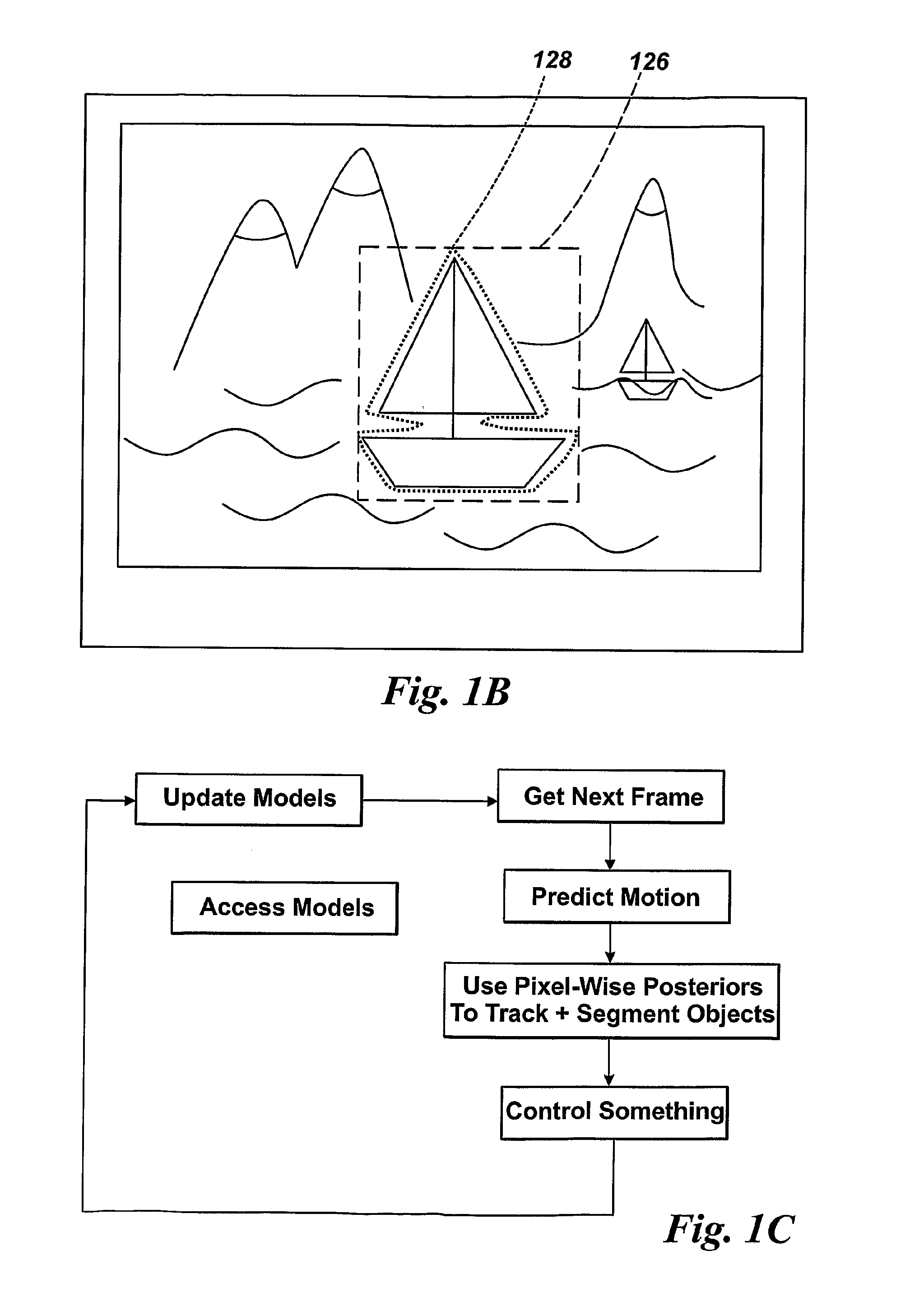
[0055]In some embodiments, only those pixels are considered that are in a narrow band around the predicted boundary contour separating object from background. This reduces the processing burden.

Problems solved by technology

However, automatically tracking targets in an image that move from frame to frame is not so easy.
One known problem is deciding from frame to frame which pixels in each image frame are part of the object / target, sometimes termed foreground, and which are the background—i.e.
It is therefore not desirable to have a fixed, single, predicted shape for the target boundary shape.
Though it has been the subject of intense effort over the last two decades, it remains a difficult problem for a number of reasons.
In particular, when tracking previously unseen objects, many of the constraints that give reliability to other tracking systems—such as strong prior information about shape, appearance or motion—are unavailable.
One technical difficulty is finding in an image where the object is located.
A second technical difficulty is dealing in changes in the apparent shape of an object caused by changes in the relative position and orientation of the object and the image-acquiring camera.

Method used


Image

  • Visual tracking of objects in images, and segmentation of images
  • Visual tracking of objects in images, and segmentation of images
  • Visual tracking of objects in images, and segmentation of images

Examples


Embodiment Construction

Section 1 Overview

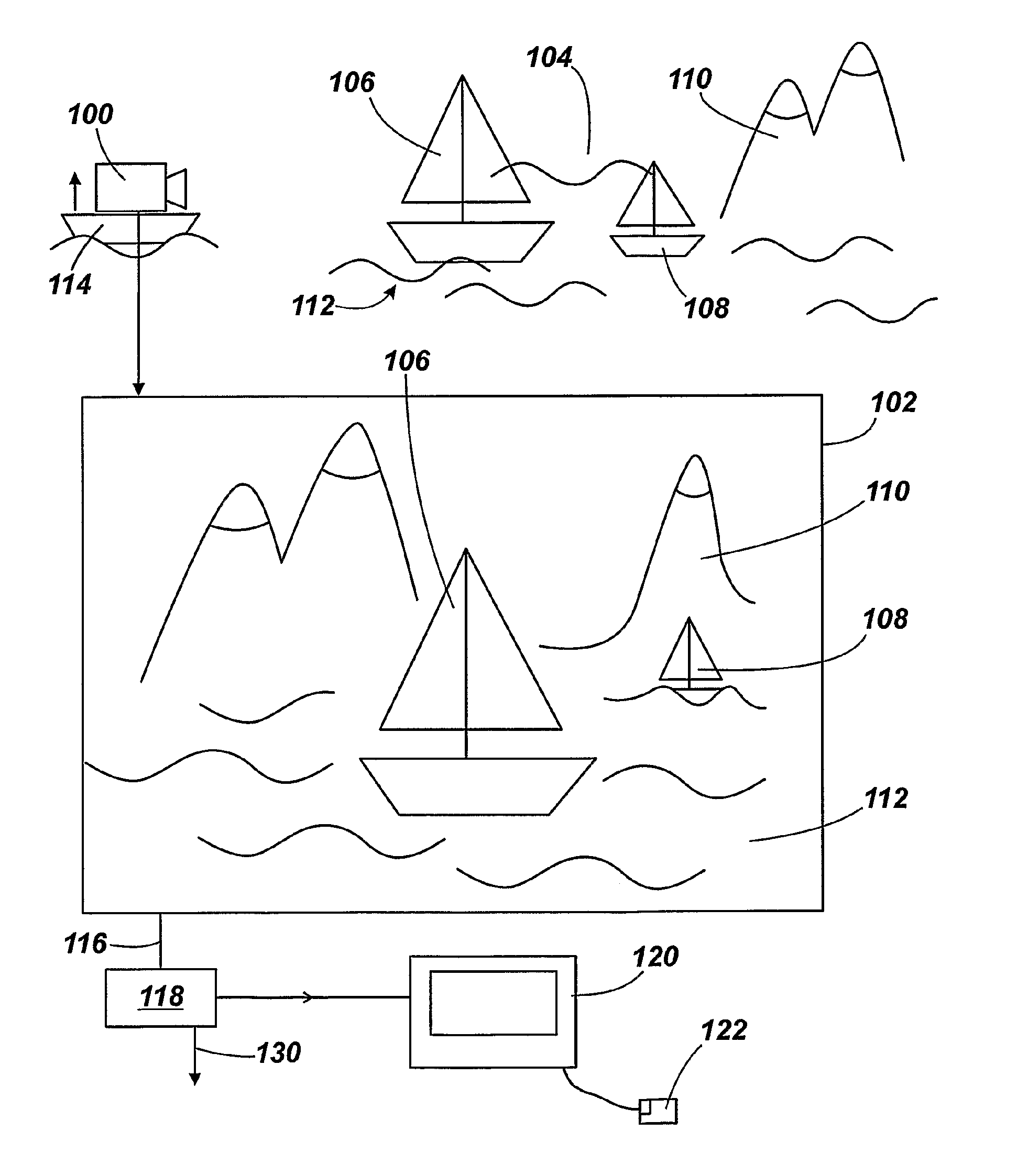
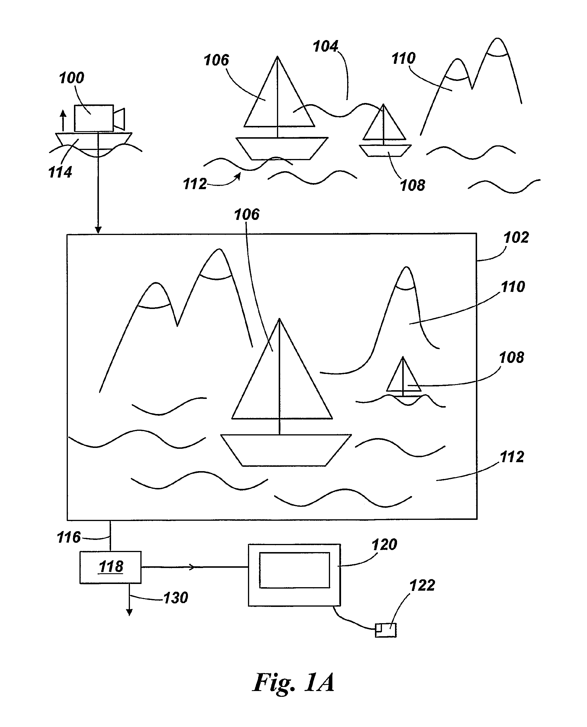
[0077]Whilst the technical detail of how we perform at least the task of delineating object from background is a significant advance over the prior art, and is the provider of technical advantages over technical problems in the prior art, it will be helpful to set the scene for the invention. There follows a discussion of the overall aim of the method and apparatus.

[0078]In many embodiments of the invention / practical applications of the invention, the overall aim is to control or modify something using an output from image processing. That “something” can be to control the movement of a camera to track an object in a field of view of the camera. That “something” can be to control or modify a digital video or image signal to centre an object in the image (or otherwise control its position in the image). That “something” can be to stabilise a digital video or series of images to reduce the effect on the images of camera shake or other relative movement between the ob...


PUM


Abstract

A method is discussed of tracking objects in a series of n-D images (102) that have objects (106, 108) appearing in a background (110, 112), that method comprises using a probabilistic model of the appearance of the objects and of the appearance of the background in the images, and using an evaluation of whether particular pixels in the images (102) are a part of an object (106, 108) or a part of the background (110, 112), that evaluation comprising determining the posterior model probabilities that a particular pixel (x) or group of pixels belongs to an object or to the background, and further comprising marginalising over these object / background membership probabilities to yield a function of the pose parameters of the objects, where at least the object / background membership is adjudged to be a nuisance parameter and marginalised out.

Description

RELATED APPLICATIONS INFORMATION[0001]This application claims the benefit of priority as a national stage of International Application No. PCT / GB2009 / 002425, filed on Oct. 9, 2009, entitled “VISUAL TRACKING OF OBJECTS IN IMAGES, AND SEGMENTATION OF IMAGES,” which in turn claims priority to Great Britain Patent Application No. GB0818561.3, filed on Oct. 9, 2008, entitled “VISUAL TRACKING OF OBJECTS IN IMAGES, AND SEGMENTATION OF IMAGES,” both of which are incorporated herein by reference in their entirety as if set forth in full.BACKGROUND[0002]1. Field of the Invention[0003]This invention relates to the visual tracking of objects in captured digital images, and segmentation of images, and the uses of such tracking, including (but not limited to) the control of camera(s) to track object(s) as the object(s) and / or the camera(s) move.[0004]2. Background of the Invention[0005]Tracking objects, or targets, in a series of captured 2-D images (e.g. an image from a digital video camera, or ...

Claims


Application Information

Patent Timeline
Patent Type & Authority Applications(United States)
IPC IPC(8): H04N7/18G06K9/34G06K9/46
CPCG06T7/0081G06T7/0087G06T2207/20161G06T2207/10016G06T2207/20076G06T7/0089G06T7/11G06T7/143G06T7/149
Inventor BIBBY, CHARLES COLINREID, IAN DAVID
Owner OXFORD UNIV INNOVATION LTD
Learn More