
Vehicle control apparatus

Inactive Publication Date: 2011-10-20
DENSO CORP +1
View PDF5 Cites 23 Cited by
  • Summary
  • Abstract
  • Description
  • Claims
  • Application Information

AI Technical Summary

Benefits of technology

[0012]An embodiment provides a vehicle control apparatus which can suppress decrease of braking force due to the decrease of vacuum pressure in the case where an engine is stopped under idle stop control (IS control) not only when the vehicle is stopped but also when the vehicle is decelerated.

Problems solved by technology

When such a brake booster is used in the control system for automatically stopping and restarting an engine, the negative pressure for the booster is decreased when the engine is stopped, resulting in decrease of the braking force.
However, an engine may be stopped under the IS control not only when the vehicle is stopped but also when the vehicle is decelerated.
The driver's frequent brake operation may decrease the vacuum pressure.
However, restart of an engine in these manners may invite a response delay.
Specifically, it may take time from when the engine is restarted until when the vacuum pressure is guaranteed, leading to difficulty in suppressing decrease of braking force.
In this case, however, the frequency of performing idle stop is lowered and thus the effect of improving fuel consumption will not be well exerted.
Further, when an engine is restarted by a starter, it sometimes happens that the engine may not be normally restarted (e.g., restart of the engine may be delayed).
As a result, the braking force may no longer be suppressed from being decreased.

Method used


Image

  • Vehicle control apparatus
  • Vehicle control apparatus
  • Vehicle control apparatus

Examples


Embodiment Construction

[0020]With reference to the accompanying drawings, hereinafter is described an embodiment of the present invention. It should be appreciated that, throughout the specification and the drawings, identical or uniform components are designated with the same references.

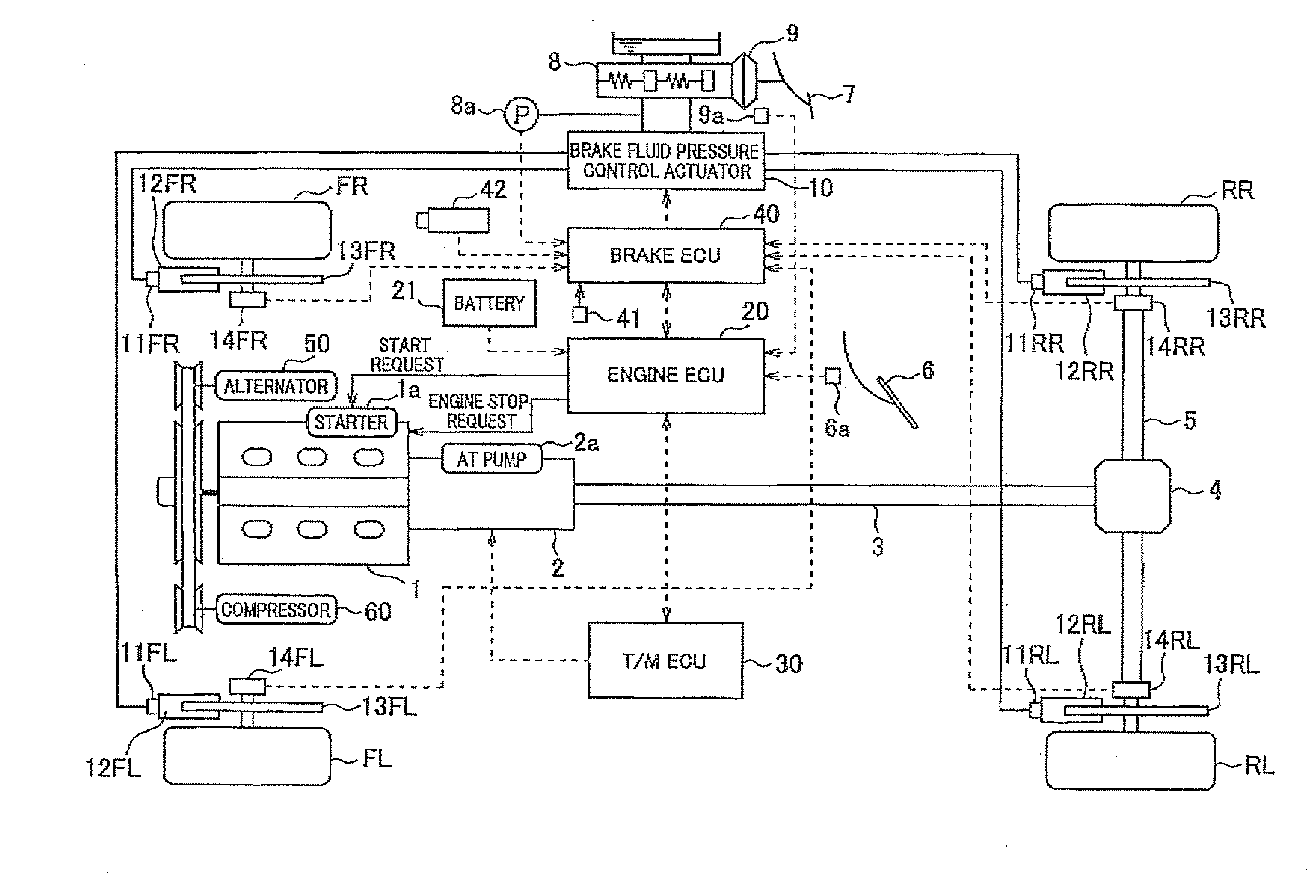
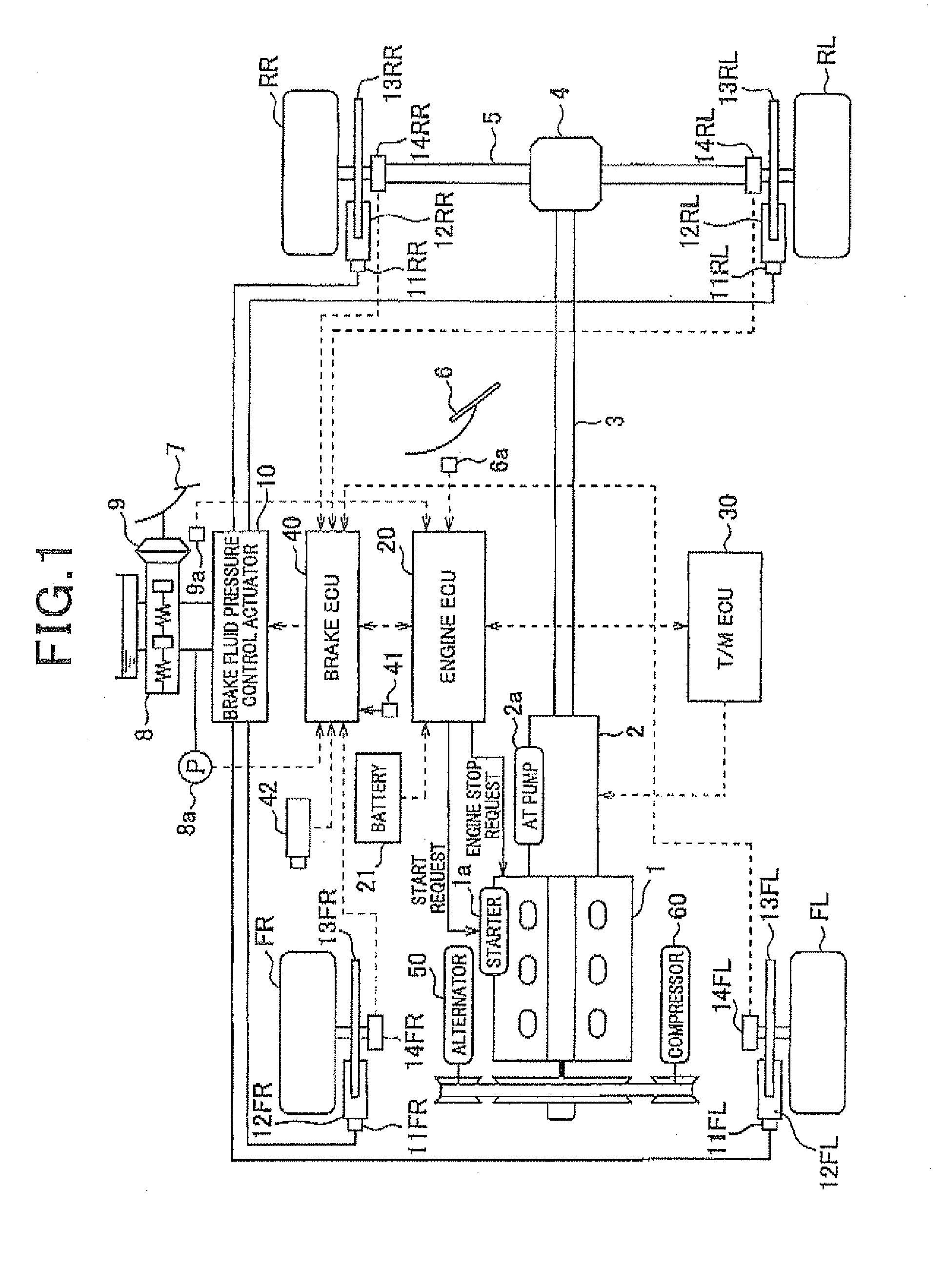
[0021]Fig, 1 is a diagram illustrating the general configuration of a vehicle control system to which a vehicle control apparatus according to the embodiment of the present invention is applied.

[0022]Specifically, the vehicle control apparatus of the embodiment is applied to an FR (front-engine rear-wheel drive) vehicle, in which an engine is installed in the front, and RR (rear-right) and RL (rear-left) wheels are used as drive wheels. However, in a similar manner, the vehicle control apparatus of the embodiment may be applied, for example, to an FF (front-engine front-wheel drive) vehicle that uses FR (front-right) and FL (front-left) wheels as drive wheels.

[0023]As shown in FIG. 1, a drive system of the FR vehicle incl...


PUM


Abstract

A vehicle control apparatus includes: an automatic-stop-and-restart-control-unit stopping / restarting an engine, a brake-fluid-pressure-control-unit controlling wheel-cylinder-pressure using a brake-system, which intensifies brake-manipulation-force by a brake-booster to cause master-cylinder-pressure in a master-cylinder while the engine operates, and which transfers the master-cylinder-pressure to wheel-cylinders to cause the wheel-cylinder-pressure, the brake-system including an actuator automatically increasing pressure in the wheel-cylinders irrespective of the brake-manipulation-force; a negative-pressure-detection-unit which detects the vacuum-pressure; a first-determination-unit which determines whether the vacuum-pressure is not more than a first threshold while the engine stops, a restarting-unit which allows the automatic-stop-and-restart-control-unit to restart the engine when the first-determination-unit determines that the vacuum-pressure is not more than the first threshold; a second-determination-unit which determines whether the vacuum-pressure is not more than a second threshold; and a braking-boost-unit which allows the brake-fluid-pressure-control-unit to automatically increase the pressure in the wheel-cylinders when the second-determination-unit determines that the vacuum-pressure is not more than the second threshold.

Description

CROSS-REFERENCE TO RELATED APPLICATION[0001]This application is based on and claims the benefit of priority from earlier Japanese Patent Application No. 2010-094397 filed Apr. 15, 2010, the description of which is incorporated herein by reference,BACKGROUND OF THE INVENTION[0002]1. (Technical Field of the Invention)[0003]The present invention relates to a vehicle control apparatus that performs idle stop control (hereinafter referred to as “IS control”) under which an engine (internal combustion engine), i.e. a drive source of travel, is stopped when predetermined conditions are met to perform idle stop.[0004]2. (Related Art)[0005]In a braking system, a pedal pressure, which is a pressure caused when a brake pedal is pressed by a driver, is intensified by a servomechanism to cause high pressure in a master cylinder (this pressure is hereinafter referred to as “M / C pressure”). The M / C pressure is then transferred to each wheel cylinder to cause high pressure in the wheel cylinder as ...

Claims


Application Information

Patent Timeline
IPC IPC(8): B60W10/18B60W50/00B60W10/04B60T8/00B60T13/60B60T17/00F02D17/00F02D29/02
CPCB60W10/06B60W10/184B60W30/18072B60W30/18136B60W30/192Y10T477/81B60W2540/12F02N11/084F02N2200/0807Y02T10/48Y10T477/814B60W2510/0671Y02T10/40
Inventor SAITO, TATSUYASATOH, TAKASHIOHMORI, YOSUKETAKEDA, MASAYOSHI
Owner DENSO CORP
Learn More