Beating and pressing plate structure, feeding mechanism and IC carrier plate processing equipment

A technology of plate structure and pressing plate, which is applied in the direction of metal processing equipment, welding equipment, welding equipment, etc., can solve the problems of inability to realize fully automatic marking work, complex and complicated equipment structure, etc.

Active Publication Date: 2021-09-10
WUHAN HGLASER ENG CO LTD
View PDF7 Cites 0 Cited by
  • Summary
  • Abstract
  • Description
  • Claims
  • Application Information

AI Technical Summary

Problems solved by technology

[0003] However, most of the existing equipment has a complex structure, which cannot realize fully automatic marking work, and the cost is too high
In addition, most of the marking targets of existing marking equipment are one side. If other sides are to be marked, human assistance is needed to turn over the other side; and in terms of loading and unloading, manual loading is often used, which affects the work. Efficiency; the adaptability of conventional manipulators for loading and unloading is low, and it is necessary to replace different types of grasping structures according to different material sizes, which is more complicated; the existing feeding mechanism can only send one time at a time, which is inefficient, and the feeding time is high. Material stripping is easy to occur during the process; the conventional visual recognition module can only take pictures of one viewing angle, and the adaptability is low; in addition, the existing laser marking system is inconvenient to adjust the coaxiality of the beam and the optical device, which is often accompanied by errors

Method used


Image

  • Beating and pressing plate structure, feeding mechanism and IC carrier plate processing equipment
  • Beating and pressing plate structure, feeding mechanism and IC carrier plate processing equipment
  • Beating and pressing plate structure, feeding mechanism and IC carrier plate processing equipment

Examples


Embodiment 1

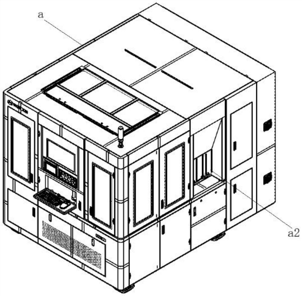
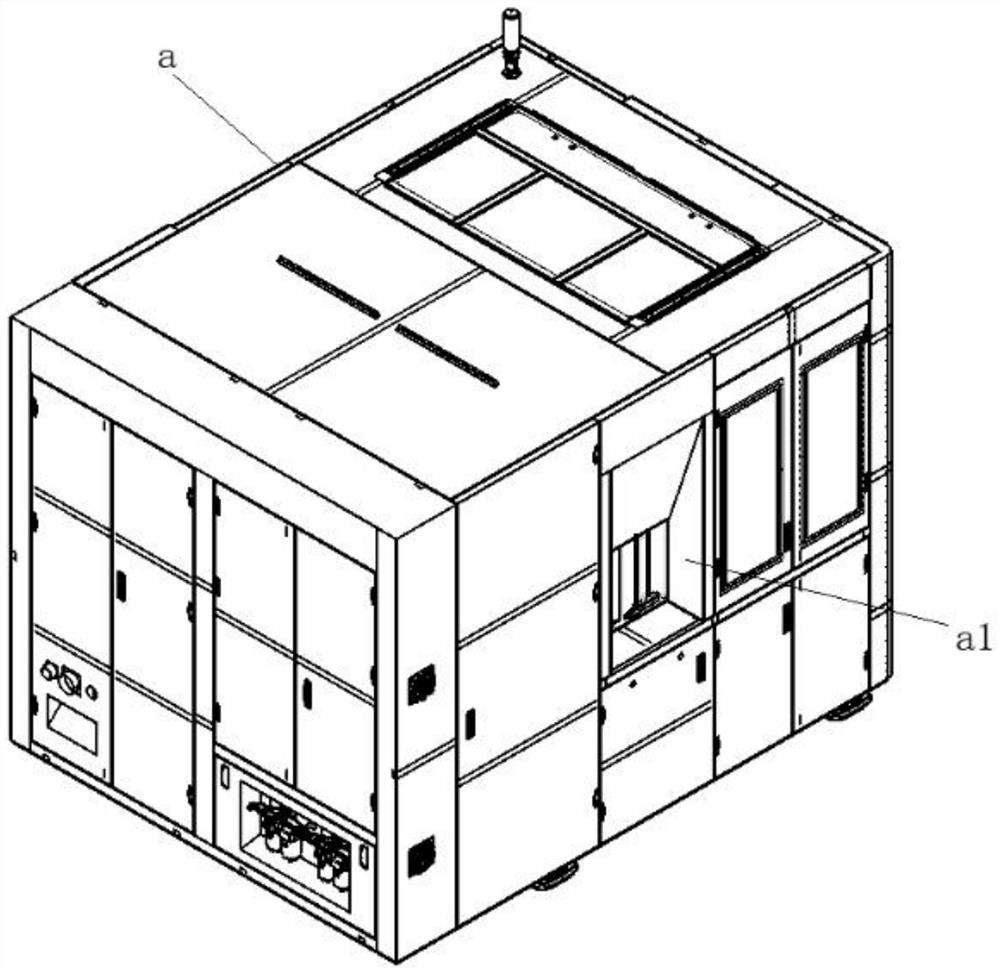
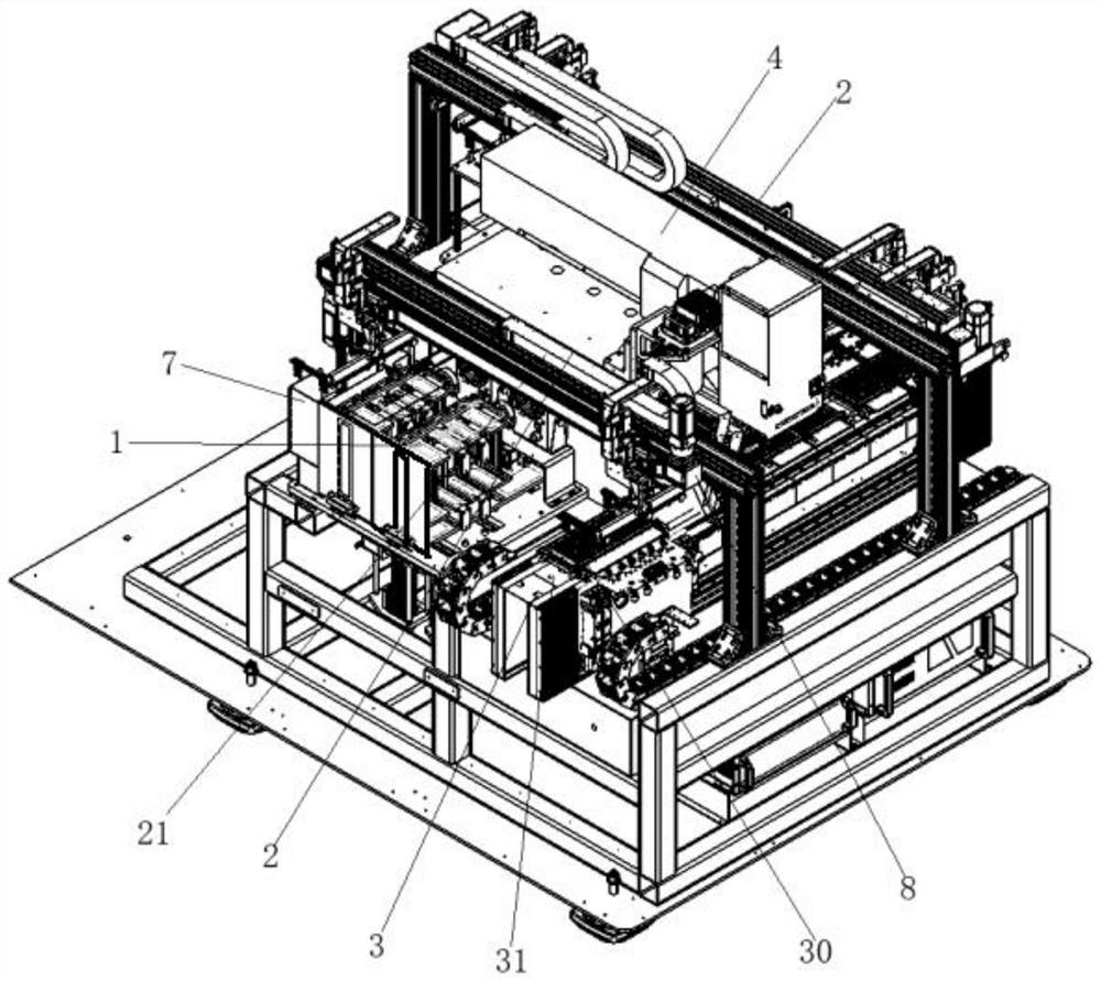
[0044] see Figure 1 to Figure 23 , The embodiment of the present invention provides an IC carrier board processing equipment, including a feeding bin 1, a reclaiming mechanism 2, a feeding mechanism 3, a marking system 4, a turning mechanism 5 and a feeding bin 6. The upper silo 1 is used to temporarily store IC carriers, and the reclaiming mechanism 2 is used to take out the IC carriers from the upper silo 1 and send the processed IC carriers to the lower silo 6 , the feeding mechanism 3 is used to send the IC carrier board taken out from the loading bin 1 by the reclaiming mechanism 2 to the marking system 4 for processing, and the marking system 4 is used for processing the IC The carrier board is processed, the turning mechanism 5 is used to turn the IC carrier board over and then send it to the marking system 4 for further processing, and the unloading bin 6 is used to temporarily store the processed IC carrier board. In this embodiment, feeding, feeding, identifying, m...

Embodiment 2

[0054] see Figure 3 to Figure 10 , the embodiment of the present invention provides an upper bin, including a carrier plate 17 for shelving stacked materials, a sensor 10 for sensing the height of the piled material, and a signal for driving the carrier plate according to the signal fed back by the sensor 10 17 a driving mechanism 11 for lifting, the driving mechanism 11 includes a driving shaft, the bearing plate 17 is arranged horizontally, the driving shaft is located below the bearing plate 17 and is arranged vertically to the bearing plate 17 . In this embodiment, the height of the stack can be sensed to automatically adjust the height of the carrying plate 17 to realize automatic feeding. Specifically, after multiple IC carriers are stacked in the loading bin, no matter how high the IC carriers are stacked, the IC carrier will be lifted to the highest position under the cooperation of the drive mechanism 11 and the sensor 10. , that is to ensure that the uppermost IC c...

Embodiment 3

[0061] see Figure 11 and Figure 12 , the embodiment of the present invention provides a material retrieving mechanism, including two columns 20 arranged oppositely and a beam 21 arranged between the two columns 20, the beam 21 is provided with a gripper assembly for grabbing materials 22. The gripper assembly 22 includes several gripping heads 23 capable of grabbing materials, several installation rods 24 for the grippers 23 to install, and a combination rod 25 for the installation rods 24 to install. The combination rods 25 There are a plurality of mounting positions for connecting the mounting rods 24 on the top, the distance between every two mounting positions can be adjusted, and each grabbing head 23 encloses a grabbing section for grabbing materials. In this embodiment, the beam 21 is supported by the column 20, so that the handle assembly 22 is suspended. When grasping, the gripper assembly 22 is driven to move downward to complete the grasping action. Specificall...


PUM


Abstract

The invention relates to the technical field of laser processing, and provides a beating and pressing plate structure. The beating and pressing plate structure comprises a first push rod capable of pushing materials to a preset area of the materials, a pressing block capable of pressing the materials on the preset area and a driving assembly used for driving the first push rod and the pressing block to act; the first push rod is located on one side of the preset area. The invention provides a feeding mechanism. The feeding mechanism comprises a feeding platform and the beating and pressing plate structure, the feeding platform is provided with the preset area, and the feeding platform is arranged on one side of the first push rod. The invention further provides IC carrier plate processing equipment. The equipment comprises the beating and pressing plate structure. By means of the beating plate function, the situation that when materials are taken and placed, the position deviation of the materials is too large, machining position errors of subsequent procedures are caused, and then waste is caused can be avoided; by means of the pressing plate function, the situation that some materials warp, if the materials warp, the feeding platform cannot adsorb the materials or cannot adsorb the materials firmly, and then machining deviation is caused can be avoided.

Description

technical field [0001] The invention relates to the technical field of laser processing, in particular to a plate-beating structure, a feeding mechanism and an IC carrier plate processing equipment. Background technique [0002] Laser marking equipment is a kind of equipment that marks the corresponding marking pattern on the material by the laser at the designated position. [0003] However, most of the existing equipment has a complex structure, cannot realize fully automatic marking work, and the cost is too high. In addition, most of the marking targets targeted by the existing marking equipment are one of the sides. If you want to mark other sides, you need to manually turn over the sides; and in terms of feeding and unloading, manual feeding is also used, which affects the work. Efficiency; conventional manipulators have a low fit for loading and unloading, and need to replace different types of grasping structures according to different material sizes, which is more ...

Claims


Application Information

Patent Timeline
Patent Type & Authority Applications(China)
IPC IPC(8): B23K26/70B23K26/362B23K37/04
CPCB23K26/70B23K26/362B23K37/0443
Inventor 王建刚刘伟周松文杜星宇
Owner WUHAN HGLASER ENG CO LTD
Why Eureka
Try Eureka