Soil solidifier and related methods

a technology of soil solidifier and soil layer, which is applied in the direction of dragees, plastic/resin/waxes insulators, pharmaceutical delivery mechanisms, etc., can solve the problems of soil being constantly shifting and reactive, and the surface deformation or fracture, etc., to achieve the effect of more rapid and easy installation

Inactive Publication Date: 2011-10-20
SB INDS
View PDF0 Cites 1 Cited by
  • Summary
  • Abstract
  • Description
  • Claims
  • Application Information

AI Technical Summary

Benefits of technology

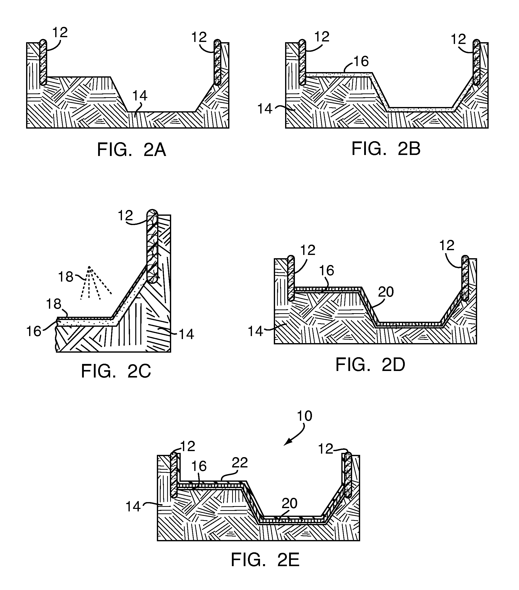
[0017]The present invention is directed to an improved method for installing structures, such as swimming pools, into or onto soil. The present invention is also directed to an improved arrangement for a structure, such as a swimming pool, that is installed into or onto soil. The present invention is further directed to a solidifier solution that may be used to solidify or plasticize materials, such as soil, for any reason. Field testing of the compounds and methods disclosed herein have demonstrated that standard structures, such as sand-bottomed swimming pools, may be installed more quickly and easily than according to currently known methods.
[0020]In accordance with yet another aspect, the present invention is directed to a solidifier solution for use in the construction of a structure, such as a swimming pool, into or onto soil. A solidifier solution according to the present invention may be a fast-curing binder solution that may be applied to a material such as sand, in order to impart strength to the material and to form a smooth polymer-based composite layer that can harden in a relatively short period of time. According to another embodiment of the present invention, the solidifier solution may comprise a polymer. According to another embodiment of the present invention, the solidifier solution may comprise a polymer and a surfactant. According to another embodiment of the present invention, the solidifier solution may comprise a polymer, a cross-linking agent, and a surfactant, which are combined by mixing. According to a currently preferred embodiment, the polymer is an aqueous emulsion polymer solution.
[0021]According to one embodiment of the present invention, one preferred polymer for use in the solidifier solution is an acrylate emulsion polymer in solution. According to another embodiment of the present invention, the solidifier solution may comprise styrene acrylate. According to one embodiment of the present invention, the polymer may be formed from monomers, such as styrene acrylate and n-butyl acrylate. According to another preferred embodiment of the present invention, the solidifier solution is sufficiently viscous and may be applied by spraying, such as onto sand.
[0022]The compounds and methods of the present invention provide a number of advantages over the prior art. For example, applying a solidifier solution according to the present invention to soil may result in a hard, smooth bottom for a structure, such as a swimming pool, less expensively and more efficiently than according to prior art methods, such as those prior art methods which utilize cement, concrete or vermiculite. The use of a solidifier solution can also reduce or eliminate the need to buy, transport and / or mix certain products, and thus reduce the cost, equipment and manual labor required to construct the pool. Additionally, structures that are constructed with a composite layer comprising a polymer and at least a portion of the sub-base in a polymer lattice using the compounds and / or methods of the present invention may save money and resources over time. In the particular example of a swimming pool constructed using the compounds and / or methods of the present invention, replacing a pool liner in the future may be performed more quickly and easily, because the pool bottom should remain in substantially the same form that was established during the initial installation.
[0023]In addition to swimming pools, which generally contain standing water, the compounds and methods disclosed herein may be used to construct or improve other water features, such as irrigation channels, drainage paths or ducts, ponds, estuaries, moats or any other applications designed to accommodate flowing or standing water. Moreover, the compounds and methods disclosed herein may also be utilized to construct or improve a variety of other permanent or semi-permanent structures which require an interface with soil, such as cofferdams, slabs, footings, sidewalks, streets, highways and the like. In addition to sand, the solidifier solutions of the present invention may also be applied to an unlimited number of materials, such as soils of any composition. For example, the solidifier solutions of the present invention may be applied to masonry, stones, concrete, pavement or other surfaces to provide greater durability and protection, as well as a smooth, high-sheen surface texture. The solidifier solution may also be included as an ingredient in other mixes, such as cement mixes, to provide a harder, stronger finished product.

Problems solved by technology

Due to the changing and sometimes unpredictable nature of soil, installing structures on or beneath the surface of the Earth can be a challenge.
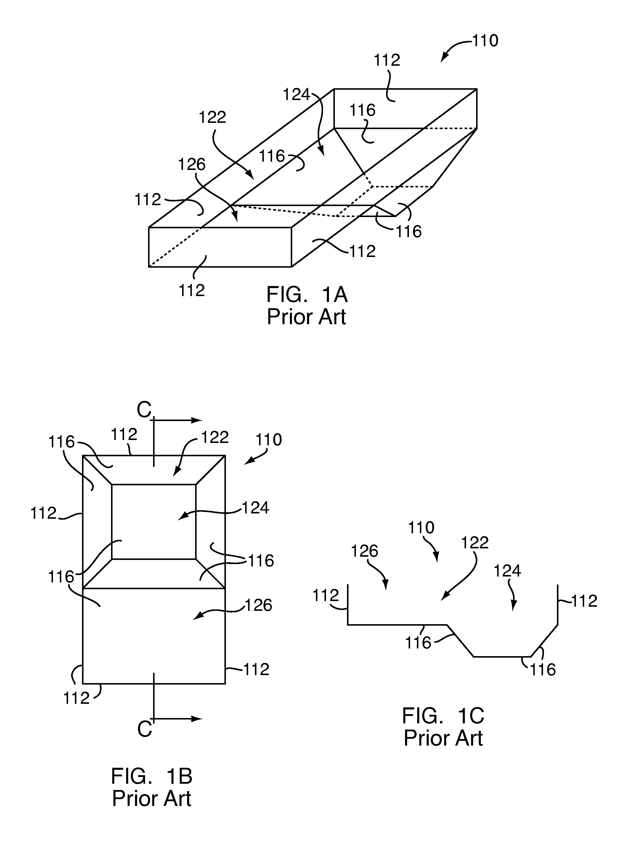
Pool bottoms, and portions of pool sidewalls which extend even slightly below grade, are subject to the constantly shifting and reactive nature of soil.
However, an empty pool is subject to potentially varying conditions in the underlying and surrounding soil, which may cause even well-formed pool surfaces to deform or fracture, requiring added work or repairs in order to complete the construction of the pool.
However, constructing a pool from cement and / or concrete may be expensive, hazardous and potentially harmful to the environment.
Moreover, cement-bottomed pools are not immune to some of the problems associated with shifting or changing soils.
For example, standard cements are typically impermeable to water, and a cement pool bottom in an unfilled pool can “float,” or “lift” up from the ground, due to soil pressures on the bottom and side surfaces of the pool, which may cause some or all of the pool bottom to crack or even shear.
However, the use of vermiculite includes many of the same challenges that are typically associated with concrete, in that vermiculite is relatively expensive and requires the purchase and delivery of materials to the site, and also requires additional labor and equipment for construction.
Moreover, a pool bottom made with vermiculite can take several days to harden, which delays the construction process.
The cost of such delays is borne by the buyer.
However, one of the most significant disadvantages of sand is its lack of independent structural strength.
During installation, a sand pool bottom may be subject to creep before the liner is installed and the pool is filled, because sand-bottomed pools rely on the hydrostatic pressure provided by the filled liner to maintain their shape.
Sand is also subject to infiltration by bugs, moles or other critters, which can damage the pool liner and threaten the pool's integrity.
Additionally, because pool liners typically must be replaced over time, the difficulties associated with building a traditional sand-bottomed pool can be encountered every time a pool liner requires replacement.

Method used


Image

  • Soil solidifier and related methods
  • Soil solidifier and related methods

Examples


example 1

[0056]A first solidifier solution (Example 1) was prepared using the acrylic-styrene emulsion polymer solution Acronal® 2835, which is produced by BASF Corporation, of Charlotte, N.C., as the monomer. Zinc Oxide #1 solution, which was produced by Johnson Polymer, of Sturtevant, Wis., was used as a cross-linking agent. Additionally, Surfynol® DF-66, which is produced by Air Products and Chemicals, Inc., of Allentown, Pa., was used as a surfactant.

[0057]Acronal® 2835 is an acrylic polymer latex with approximately 50% solids by weight, a viscosity of approximately 300 cps, a density of approximately 8.7 pounds per gallon, and a glass transition temperature of 20° C. Acronal® 2835 is a basic solution with a milky white liquid and an acrylic odor. Acronal® 2835 has a specific gravity of 1.1, a pH of approximately 9.0, and 47.5% volatile organic compounds by weight.

[0058]Zinc Oxide #1 comprises carbonic acid and salts of ammonium and zinc, such as zinc ammonium carbonate, in solution. Zin...

example 2

[0061]A second solidifier solution (Example 2) was prepared using the acrylic-styrene emulsion copolymer marketed under the name Texicryl® 13-061, which is produced by Scott Bader, Inc., Stow, Ohio, as the monomer. Zinc Oxide #1 was used as the cross-linking agent, and Surfynol® DF-66 was used as the surfactant.

[0062]Texicryl® 13-061 is a 50% styrene acrylic copolymer latex, modified to include silane incorporated into the polymer backbone, in order to improve its flexibility and water resistance. Texicryl® 13-061 has approximately 50% solids by weight, and a specific gravity of 1.02, a viscosity of 50-200 cps, a pH of 7.0 to 8.5, a glass transition temperature of 11° C. Texicryl® 13-061 also has a minimum film forming temperature of 0° C.

[0063]The Example 2 solution was formed using 80% Texicryl® 13-061, 2% Zinc Oxide #1 solution and 18% water by volume, plus approximately three drops of Surfynol® DF-66 as a surfactant. The Example 2 solution was formed by mixing the ingredients, a...


PUM

PropertyMeasurementUnit
diameteraaaaaaaaaa
diameteraaaaaaaaaa
diameteraaaaaaaaaa

Abstract

A method for constructing a structure, preferably a swimming pool, includes the steps of excavating a cavity, applying a sub-base such as sand along at least a portion of the cavity, forming the sub-base into the desired shape of the structure, and applying a solidifier solution to the sub-base. The solidifier solution comprises a polymer in solution. The solidifier solution and the sub-base harden to form a smooth, hard composite layer in the base of the cavity, with the composite layer containing at least some of the polymer and at least some of the sub-base in a polymer lattice. After the solidifier solution has been applied, a liner may be installed, and the swimming pool may be filled. Additionally, the solidifier solution may be applied directly to the cavity, or to masonry or other materials, and may be used to construct any applicable structure.

Description

CROSS-REFERENCE TO RELATED APPLICATIONS[0001]This application is a continuation-in-part of U.S. patent application Ser. No. 12 / 761,999, filed Apr. 16, 2010, the contents of which are incorporated herein by reference in their entirety.BACKGROUND OF THE INVENTION[0002]1. Field of the Invention[0003]The present invention relates to systems and methods for installing structures at or below earth grade. More particularly, the present invention relates to the use of improved materials and methods to install structures at or below earth grade, such as swimming pools, in order to provide an improved interface between the structure and the soil in situ.[0004]2. Description of the Related Art[0005]Due to the changing and sometimes unpredictable nature of soil, installing structures on or beneath the surface of the Earth can be a challenge. In its natural state, soil may comprise three phases, including air, solids and water. Generally, soil solids may include any combination of sands (such as...

Claims


Application Information

Patent Timeline
Patent Type & Authority Applications(United States)
IPC IPC(8): C08K13/02C08L25/14C08K3/28C08K5/5425C08K5/42
CPCC08K3/28
Inventor OAT, JOANNADE KROM, ADRIANSHAW, JR., ROBERT M.
Owner SB INDS
Why Eureka
Try Eureka