Solar Energy Absorber

a solar energy and absorber technology, applied in the field of solar energy absorbers, to achieve the effect of reducing heat loss and easy entry into the container parts

Inactive Publication Date: 2011-10-27
ELECTRA HLDG CO LTD
View PDF0 Cites 11 Cited by
  • Summary
  • Abstract
  • Description
  • Claims
  • Application Information

AI Technical Summary

Benefits of technology

[0020]According to the present invention, by comprising the opened container part that accumulates heat, the closed part that closes the container part and has an opening part to let the collected solar light in, and the light absorbing part that absorbs the solar light dispersed by passing through the opening part so that it is converted into heat; the collected solar light enters the container par...

Problems solved by technology

In particular, how to take advantage of the abundant energ...

Method used


Image

  • Solar Energy Absorber
  • Solar Energy Absorber
  • Solar Energy Absorber

Examples


embodiment 1

[0043]First, with Reference to the Drawings, the Schematic Configuration and Functions of the solar heat collecting apparatus regarding the first embodiment according to the present invention is described. Although the drawings are used for describing the present invention which solves the above-described problem, the present invention shall not be limited to the embodiment illustrated in the drawings.

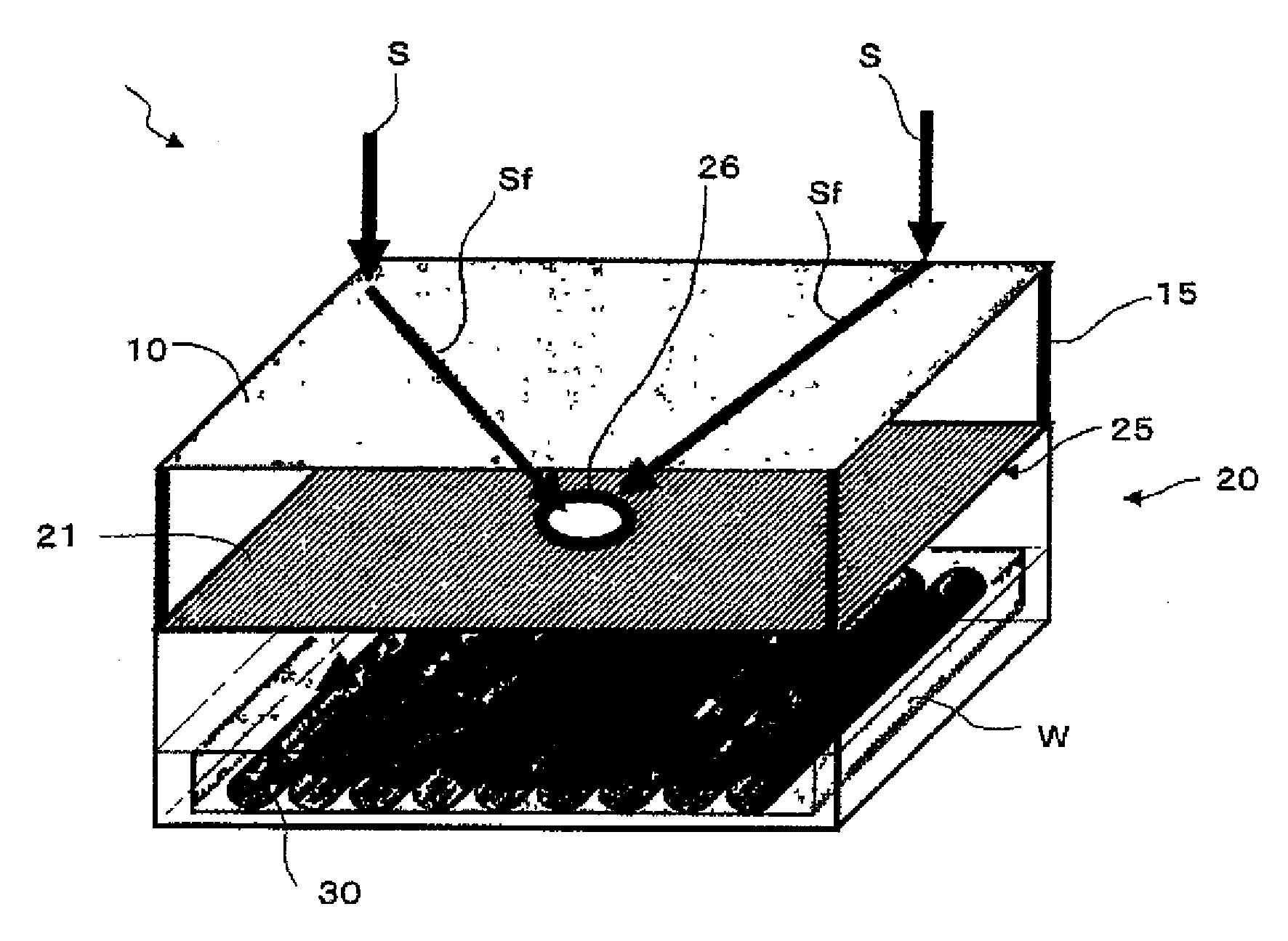
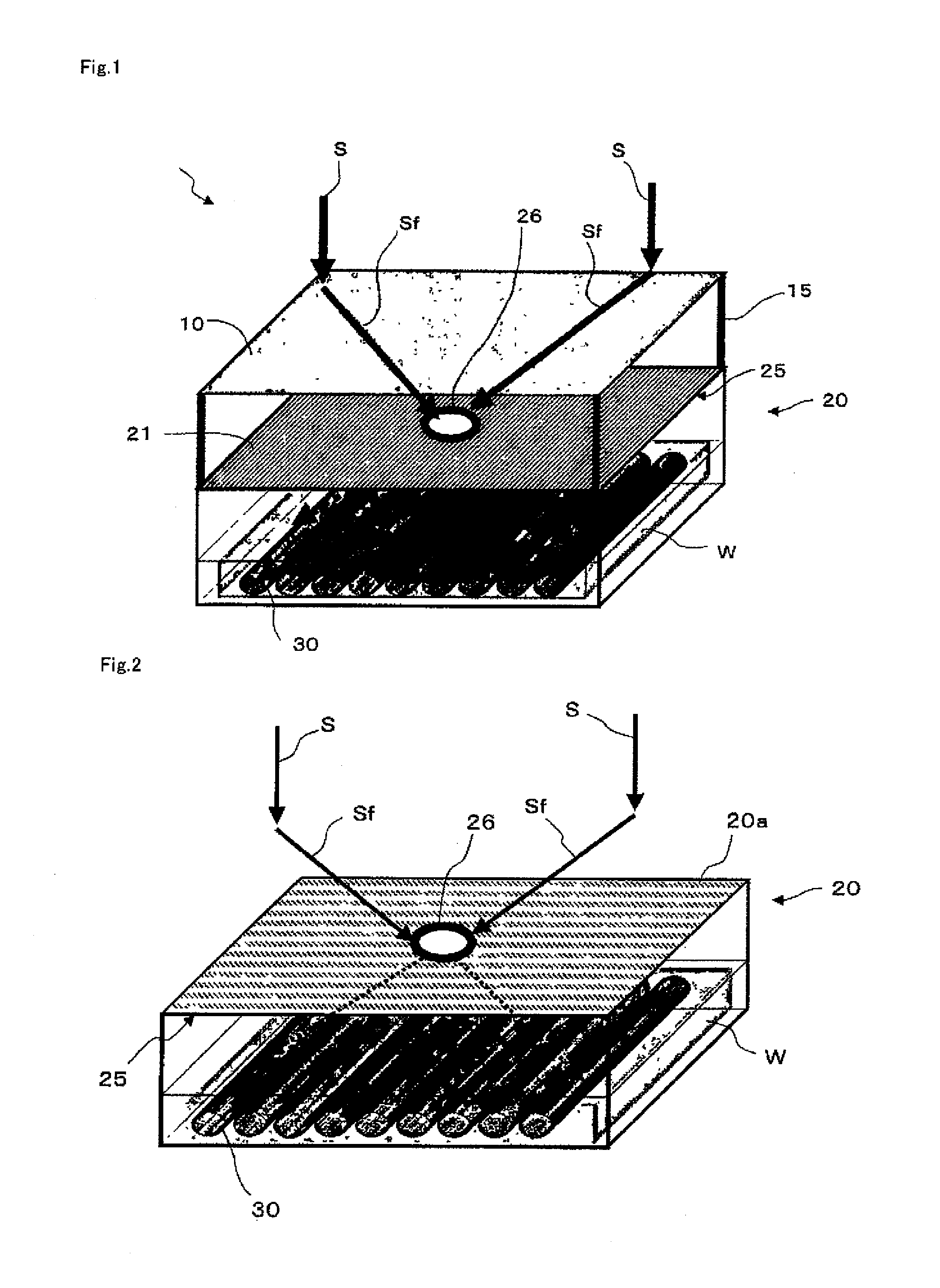
[0044]FIG. 1 shows a schematic diagram that illustrates a schematic configuration example of the solar heat collecting apparatus regarding the first embodiment according to the present invention.

[0045]As shown in FIG. 1, the solar heat collecting apparatus 1 comprises a Fresnel lens 10 that collects the solar light S, a heat-insulated water tank 20 that has an opened upper part 20a and accepts the solar light Sf that is collected by the Fresnel lens 10 to accumulate the heat of the solar light, a visor 25 that is an example of the closed part that closes the upper part 20a of the heat-...

embodiment 2

[0069]Next, the solar heat collecting apparatus regarding the second embodiment according to the present invention is described.

[0070]First, the schematic configuration of the solar heat collecting apparatus regarding the second embodiment is described with reference to the figure. Like symbols are used for like or the corresponding parts as the first embodiment, and only different configurations and functions are described. It shall be likewise for other embodiments and alternative examples.

[0071]FIG. 5 shows a schematic diagram that illustrates a schematic configuration example of the solar heat collecting apparatus regarding the second embodiment according to the present invention, and also shows a schematic diagram of the solar heat collecting apparatus that addresses the diurnal motion of the sun. Furthermore, FIG. 5 indicates the arrangement that considers the diurnal motion of the sun.

[0072]As shown in FIG. 5, the solar heat collecting apparatus 2 has a visor 25B and slit 26B...

embodiment 3

[0099]Next, the solar heat collecting apparatus regarding the third embodiment according to the present invention is described.

[0100]FIG. 10 shows a schematic diagram that illustrates a schematic configuration example of the solar heat collecting apparatus regarding the third embodiment according to the present invention. FIG. 10 also shows the principle of the means to solve the problem etc. of having less amount of solar light that enters the lens as the solar light comes down to the direction of the horizon.

[0101]As shown in FIG. 10, the solar heat collecting apparatus 3, in contrast to the solar heat collecting apparatus 1 of FIG. 1, comprises the tracking means 40 that tracks the sun in accordance with the movement of the sun.

[0102]The tracking means 40 has a rotation axis (for example, diurnal motion adjusting axis) 41, and arms 42 that are rotatably installed at the rotation axis 41. The rotation axis 41 is positioned on the side of the upper part of the heat-insulated water ...


PUM


Abstract

It aims to provide a solar heat collecting apparatus that can efficiently collect energy from solar light. The solar heat collecting apparatus comprises an opened container part 22 that accumulates heat, a closed part 25 that closes the container part 22 and has an opening part 26 to let the collected solar light in, and a light absorbing part 36 that absorbs the solar light dispersed by passing through the opening part 26 so that it is converted into heat.

Description

FIELD OF THE INVENTION[0001]The present invention is related to a solar heat collecting apparatus that collects energy from solar light.BACKGROUND OF THE INVENTION[0002]As we today are concerned about global warming, many studies have been conducted for seeking a renewable energy that does not use electricity. In particular, how to take advantage of the abundant energy from the sun is an increasingly important issue for the future. With the background, the heat collecting apparatus and desalination apparatus etc. that use the solar light are the most impending items to be realized. In order to realize these, it is necessary to efficiently absorb the heat from the solar light and increase the temperature of fluid etc. For example, Patent Document 1 discloses a heat collecting apparatus that is provided with one or more heat collecting units comprising a tubular heat collector inside which there is a path for the fluid in order to convert the received solar light into heat and to incr...

Claims


Application Information

Patent Timeline
IPC IPC(8): F24J2/08F24J2/46F24J2/38F24J2/02F24S10/80F24S20/30F24S23/00F24S23/30F24S23/70F24S23/74F24S50/20
CPCF24J2/0488F24J2/06F24J2/067F24J2/085Y02E10/47F24J2/54Y02E10/43Y02E10/44F24J2/345F24S23/00F24S23/12F24S23/31F24S30/40F24S60/30F24S70/60
Inventor YABE, TAKASHISATOH, YUJI
Owner ELECTRA HLDG CO LTD
Why Eureka
Try Eureka