Transmission line impedance transformer and related methods

Active Publication Date: 2011-10-27
HARRIS GLOBAL COMMUNICATIONS INC
View PDF0 Cites 1 Cited by
  • Summary
  • Abstract
  • Description
  • Claims
  • Application Information

AI Technical Summary

Benefits of technology

[0007]In view of the foregoing background, it is therefore an object of the present inve

Problems solved by technology

These classes of power amplifiers are more efficient than Class A or B amplifiers, for example, but are subject to performance tradeoffs.
For example, they may be nonlinear over certain frequencies and may introduce greater am

Method used


Image

  • Transmission line impedance transformer and related methods
  • Transmission line impedance transformer and related methods
  • Transmission line impedance transformer and related methods

Examples


Example

[0025]The present invention will now be described more fully hereinafter with reference to the accompanying drawings, in which preferred embodiments of the invention are shown. This invention may, however, be embodied in many different forms and should not be construed as limited to the embodiments set forth herein. Rather, these embodiments are provided so that this disclosure will be thorough and complete, and will fully convey the scope of the invention to those skilled in the art. Like numbers refer to like elements throughout.

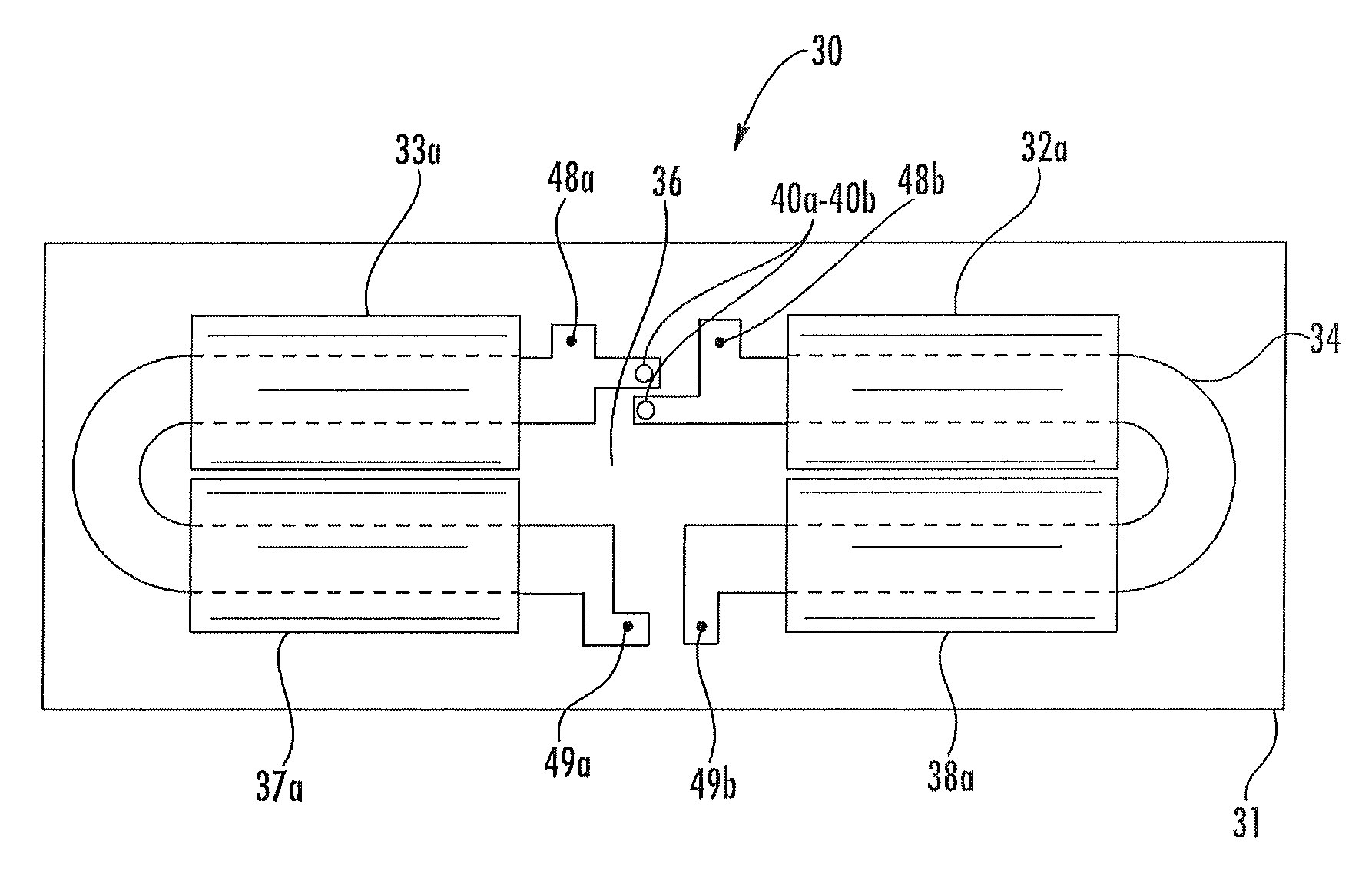
[0026]Referring initially to FIGS. 3-8, a transmission line impedance transformer 30 according to the present invention is now described. The transmission line impedance transformer 30 illustratively includes a printed circuit board (PCB) 31 comprising a dielectric layer and a pair of electrically conductive layers 34-35 on the major surfaces of the PCB. In the illustrated embodiment, the PCB 31 is planar in shape, but may have other shapes in other embodi...


PUM

PropertyMeasurementUnit
Timeaaaaaaaaaa
Electrical conductivityaaaaaaaaaa
Electrical conductoraaaaaaaaaa

Abstract

A transmission line impedance transformer may include a printed circuit board (PCB) having a dielectric layer and an electrically conductive layer thereon defining a medial interconnection portion, and first and second lateral loop portions extending laterally outwardly from opposing first and second sides of the medial interconnection portion. The PCB also may have first ferrite body receiving openings therein adjacent the first lateral loop portion and second ferrite body receiving openings therein adjacent the second lateral loop portion. The transmission line impedance transformer may also include a first ferromagnetic body extending through the first ferrite body receiving openings to surround the first lateral loop portion, and a second ferromagnetic body extending through the second ferrite body receiving openings to surround the second lateral loop portion.

Description

FIELD OF THE INVENTION[0001]The present invention relates to the field of transformers, and, more particularly, to radio frequency transmission line impedance transformers and related methods.BACKGROUND OF THE INVENTION[0002]Wireless communications devices are an integral part of society and permeate daily life. The typical wireless communications device includes an antenna, and a transceiver coupled to the antenna. The transceiver and the antenna cooperate to transmit and receive communications signals.[0003]A typical radio frequency (RF) transceiver includes a power amplifier for amplifying low amplitude signals for transmission via the antenna. Given that most mobile communications devices operate on limited battery power, energy efficient power amplifiers may be desirable. More specifically and as will be appreciated by those skilled in the art, Class C and E power amplifiers are common in certain communications devices since they are efficient power amplifiers. These classes of...

Claims


Application Information

Patent Timeline
IPC IPC(8): H01F5/02H01F41/02
CPCH01P5/10Y10T29/49073Y10T29/4902H01P5/02
Inventor MUI, ANDREW
Owner HARRIS GLOBAL COMMUNICATIONS INC
Why Eureka
Try Eureka