
Systems and methods for resolving interferometric angle-of-arrival ambiguities due to local multipath reflections

a multipath reflection and interferometer technology, applied in the field of signal processing, can solve problems such as multipath bias contamination of ambiguity vectors in some situations, and achieve the effects of facilitating the resolution of such errors, and reducing the number of errors

Inactive Publication Date: 2011-10-27
L 3 COMM INTEGRATED SYST
View PDF3 Cites 27 Cited by
  • Summary
  • Abstract
  • Description
  • Claims
  • Application Information

AI Technical Summary

Benefits of technology

"The patent describes a system and method for resolving interferometric AOA ambiguities caused by local multipath reflections. The system includes an interferometer array with multiple antenna elements and receiver circuitry for receiving emitter signals and local multipath reflections. The received signals are then processed to measure the phase differences caused by the combination of the emitter signal and the local reflections. These phase differences are used to calculate the true AOA of the emitter. The system can reclaim sections of the interferometer field of view that are known to be affected by multipath reflections. The technical effect of this patent is the improved ability to accurately determine the AOA of a signal emitter in the presence of local multipath reflections."

Problems solved by technology

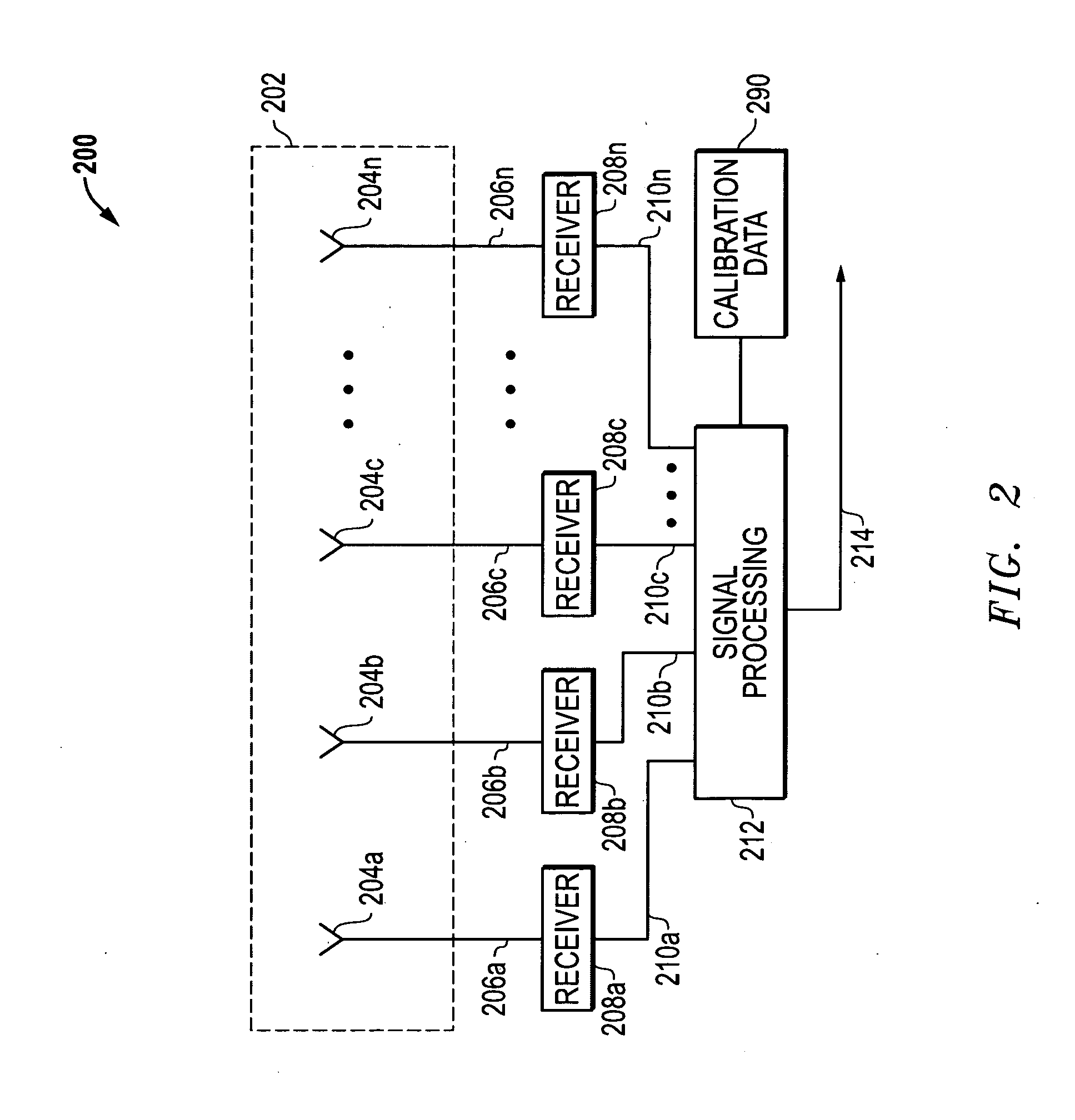
Ambiguity vectors are then generated from the interferometric phase differences, and these ambiguity vectors may in some situations be contaminated with multipath bias due to local multipath reflections which result from measurement of the vector sum of the direct (true) path and the reflected path.

Method used


Image

  • Systems and methods for resolving interferometric angle-of-arrival ambiguities due to local multipath reflections
  • Systems and methods for resolving interferometric angle-of-arrival ambiguities due to local multipath reflections
  • Systems and methods for resolving interferometric angle-of-arrival ambiguities due to local multipath reflections

Examples


Embodiment Construction

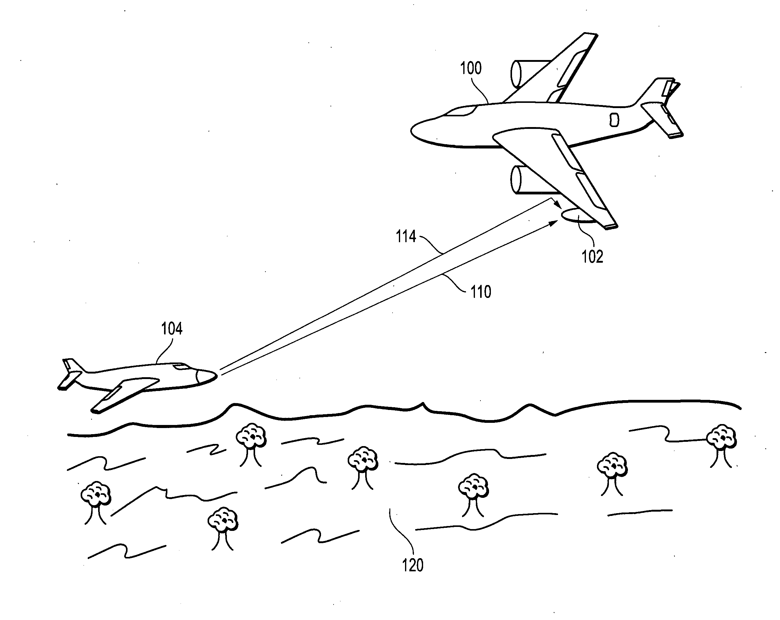
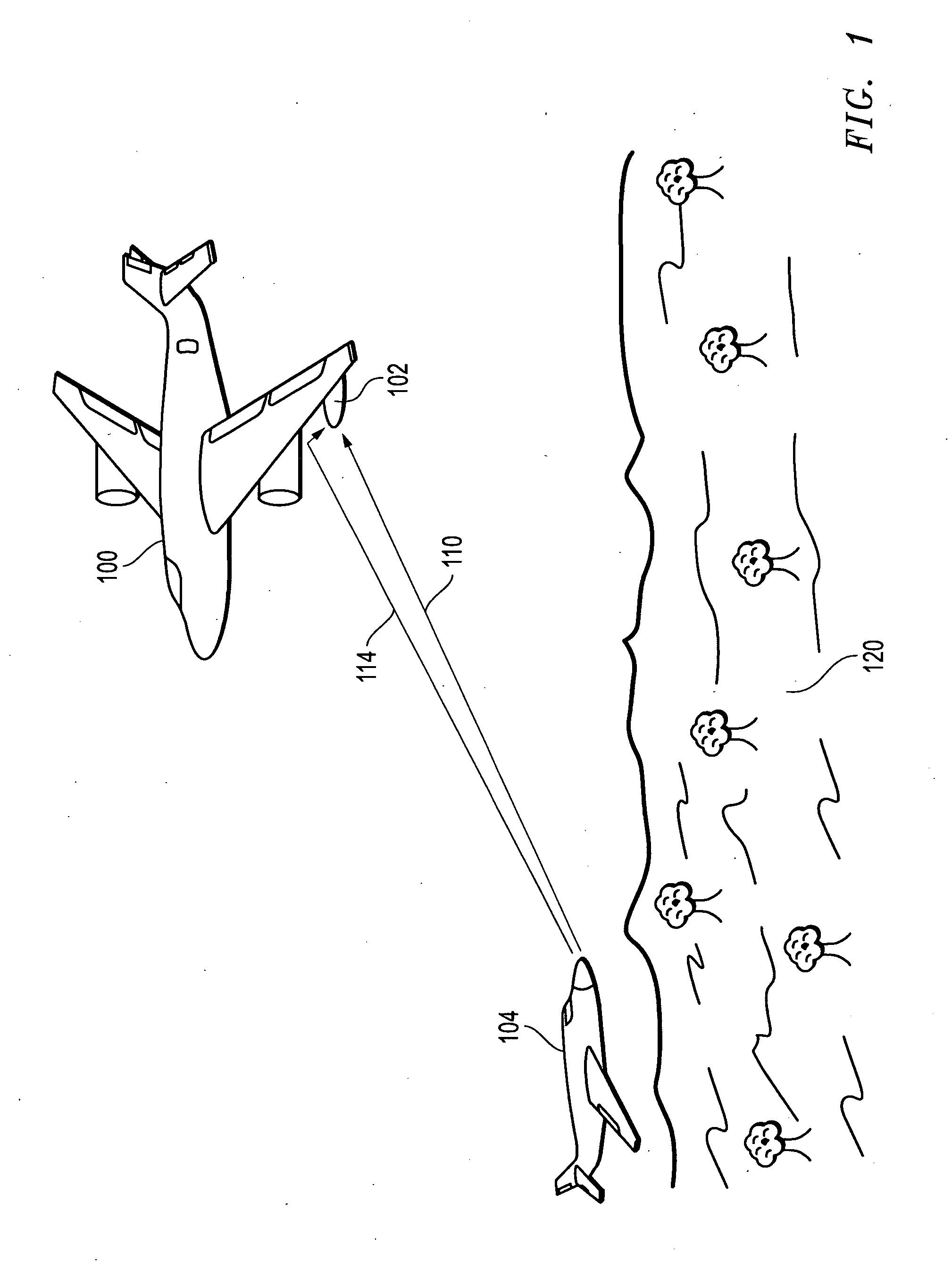
[0014]FIG. 1 illustrates a directional interferometer system platform 100 configured in this embodiment as a fixed wing aircraft. As shown, platform 100 includes a wing-mounted antenna pod 102 in which an interferometer antenna array of an interferometer system is housed. Other signal processing components of the interferometer system may be contained in pod 102, elsewhere on platform 100, and / or at a processing location that is remote from platform 100. The interferometer system uses TDOA to measure the difference in received phase of a radio frequency (RF) signal at each element in the antenna array, and then converts the measured difference to an AOA measurement for emitter 104.

[0015]It will be understood that that directional interferometer system platform of FIG. 1 is exemplary only, and that any other type of mobile or vehicle-borne or stationary platform may be employed to support a directional interferometer system, e.g., vehicle-borne platforms (such as ship, helicopter, tr...


PUM


Abstract

Interferometric angle-of-arrival (AOA) ambiguities due to local multipath reflections are resolved by measuring the received phase differences of one or more pairs of antenna elements of the interferometer array, constructing hypotheses from unwrapped phase pairs that correspond to potential AOA solutions, and selecting the hypothesis that most likely represents the true AOA of the signal emitter based on processed unwrapped data that has been corrected through the application of a priori calibration terms selected on the bases of the candidate hypotheses.

Description

FIELD OF THE INVENTION[0001]This invention relates generally to signal processing, and more particularly to interferometers.BACKGROUND OF THE INVENTION[0002]Angle of Arrival (“AOA”) is a technique employed to determine the propagation direction of a radio-frequency (“RF”) signal wave incident on a multi-element antenna array by measuring the Time Difference of Arrival (“TDOA”) of the signal at individual elements of the array. This TDOA measurement is made by measuring the difference in received phase at each element in the antenna array, and converting the measured difference to an AOA measurement. AOA technology is used for locating signal emitters such as cell phones or military transmitters, for example, to cue other precision tracking systems such as a search and track radar.[0003]AOA measurements are typically made by measuring the phase difference of a received emitter signal between pairs of antennas in an interferometer array. Interferometer arrays are often mounted on vehi...

Claims


Application Information

Patent Timeline
Patent Type & Authority Applications(United States)
IPC IPC(8): G01S3/00G01S7/40
CPCG01S3/46G01S3/10
Inventor SAPP, MICHAEL D.
Owner L 3 COMM INTEGRATED SYST
Learn More