
Multi-beam exposure scanning method and apparatus, and method for manufacturing printing plate

Inactive Publication Date: 2011-10-27
FUJIFILM CORP
View PDF4 Cites 5 Cited by
  • Summary
  • Abstract
  • Description
  • Claims
  • Application Information

AI Technical Summary

Benefits of technology

[0013]According to the present invention, the influence of heat in the vicinity of the surface shape to be left can be reduced in such a manner that the roles in the engraving are shared by each of the scanning exposure operations performed a plurality of times, and that beam power control, exposure position control, and the like, are performed in each of the exposure scanning processes. Thereby, it is possible to form a desired surface shape and inclined section (slope) with high precision.

Problems solved by technology

When a plate is engraved by such multi-beam exposure technique, it is very difficult to stably form fine shapes, such as small dots and thin lines, because of the influence of heat due to the adjacent beams.

Method used


Image

  • Multi-beam exposure scanning method and apparatus, and method for manufacturing printing plate
  • Multi-beam exposure scanning method and apparatus, and method for manufacturing printing plate
  • Multi-beam exposure scanning method and apparatus, and method for manufacturing printing plate

Examples


first embodiment

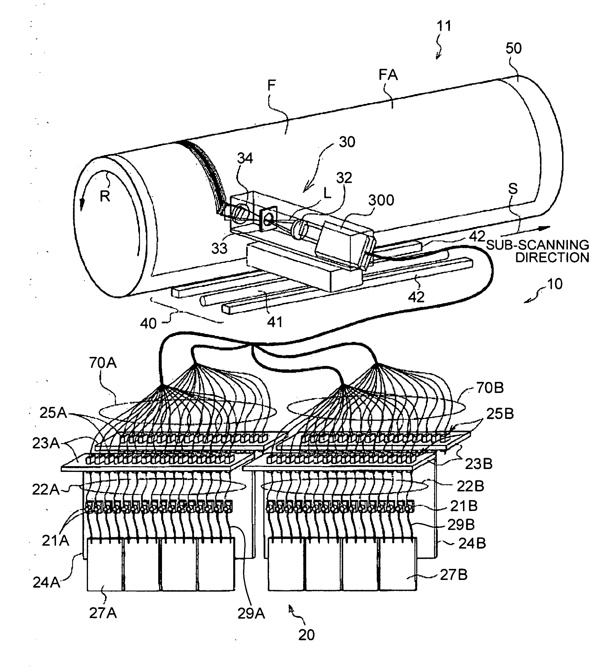
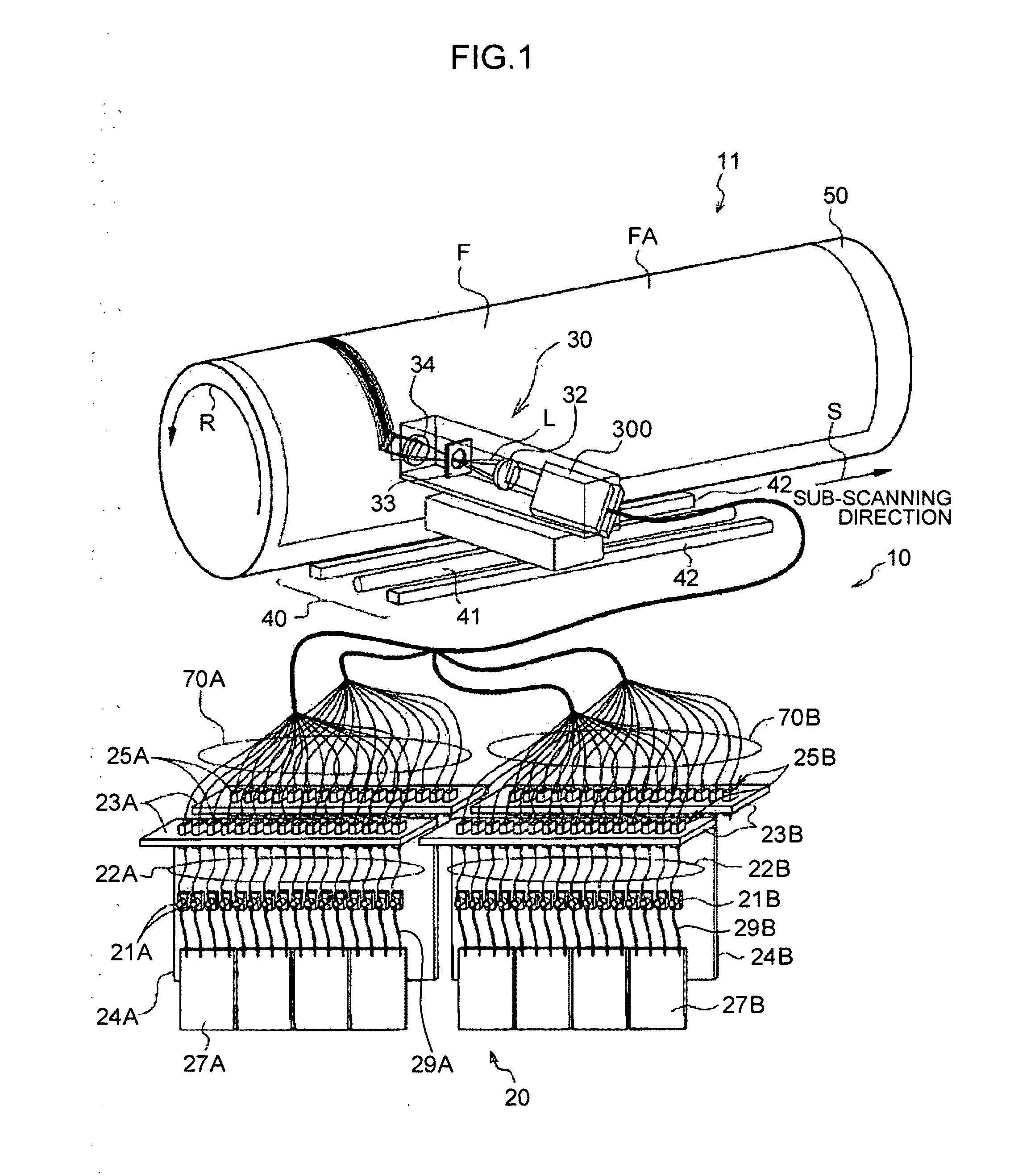
[0064]In a first method using the multi-beam exposure system which exposes and scans the same scanning lines a plurality of times, an outline of a planar shape to be left on the surface of a recording medium and an outline of an inclined section of the planar shape are formed with a first beam group (rough engraving process), and after the temperature of the plate material F increased in the rough engraving process is reduced to a predetermined temperature, the same scanning lines are exposed and scanned with a second beam group, so that a final shape (of the target surface shape and the inclined section thereof) is precisely formed by fine engraving (fine engraving process). Here, it is preferred that the energy of the second beam group irradiated to the recording medium in the vicinity of the final shape is lower than the energy of the first beam group irradiated to the recording medium. To this end, the output power of the second beam group is controlled to become lower than the ...

second embodiment

[0081]In a second method using the multi-beam exposure system which exposes and scans the same scanning lines a plurality of times, the edge section along the main scanning direction or the edge section along the sub-scanning direction, among the edge sections of the final shape to be left on the exposure surface of the recording medium, is formed with a first beam group (first direction edge forming process), and after the temperature increased by the first direction edge forming process is reduced to a predetermined temperature, the edge section perpendicular to the first direction edge is formed with a second beam group (second direction edge forming process), so that a desired final shape (a surface shape and an inclined section) is obtained. In this way, a multiple-time scanning exposure system is adopted in which the roles of engraving (roles of forming the edge section along the first direction and the edge section along the second direction) are shared by the respective beam...

third embodiment

[0090]In a third method using the multi-beam exposure system which exposes and scans the same scanning lines a plurality of times, a final surface shape to be left on the exposure surface of a recording medium is formed by exposing thin lines with a first beam group of low power so that only the edge section of the final surface shape is formed (contour line engraving process), and after the temperature increased by the contour line engraving process is reduced to a predetermined temperature, an inclined section is formed by exposing and scanning the outside of the thin lines (contour lines) with a second beam group (inclined section engraving process).

[0091]In this way, a multiple-time scanning exposure method is adopted in which the roles of engraving (roles of forming the contour line and the inclined section) are shared by the respective beam groups in a plurality of times of scanning and exposure.

[0092]Thereby, the influence of heat on the surface section to be left can be supp...


PUM


Abstract

An aspect of the present invention provides a multi-beam exposure scanning method for exposing and scanning same scanning lines a plurality of times by simultaneously irradiating an object with a plurality of light beams to engrave a surface of the object. The method includes a first exposure scanning process of forming a first shape (110), which defines an outline shape of a target planar shape (121) to be left on an exposure surface of the object and an inclined section (122) around the target planar shape (121), with a first beam group, and a second exposure scanning process of forming a second shape (120), which defines a final shape of the target planar shape (121) and the inclined section (122) around the target planar shape (121), by exposing and scanning with a second beam group the same scanning lines as the scanning lines exposed and scanned in the first exposure scanning process.

Description

TECHNICAL FIELD[0001]The present invention relates to a multi-beam exposure scanning method and apparatus. More particularly, the present invention relates to a multi-beam exposure technique suitable for manufacture of a printing plate, such as a flexographic plate, and to a manufacturing technique of a printing plate, to which the multi-beam exposure technique is applied.BACKGROUND ART[0002]Conventionally, there has been disclosed a technique which engraves a recessed shape in the surface of a plate material by using a multi-beam head capable of simultaneously irradiating a plurality of laser beams (Patent Document 1). When a plate is engraved by such multi-beam exposure technique, it is very difficult to stably form fine shapes, such as small dots and thin lines, because of the influence of heat due to the adjacent beams.[0003]In order to solve such problem, Patent Document 1 proposes a configuration which performs so-called interlace exposure to reduce mutual thermal effects betw...

Claims


Application Information

Patent Timeline
IPC IPC(8): B41J2/447
CPCB41C1/05G03F7/24G03F7/2055
Inventor MIYAGAWA, ICHIROU
Owner FUJIFILM CORP
Learn More