Microscope apparatus

a technology of microscope and microscope, applied in the field of microscope equipment, can solve the problems of reducing the resolution power, and reducing the optical performance of the objective lens

Active Publication Date: 2011-10-27
NIKON CORP
View PDF2 Cites 9 Cited by
  • Summary
  • Abstract
  • Description
  • Claims
  • Application Information

AI Technical Summary

Benefits of technology

[0018]If the microscope apparatus according to the present invention is configured as described above, entrance pupils of optical systems can be enlarged while maintaining the rotational symmetry of the optical systems of a plurality of optical paths after ejection of light from an objective lens to bring out the performance of the objective lens.

Problems solved by technology

Accordingly, the resolving power is also approximately halved, and the optical performance of the objective lens cannot be fully utilized.

Method used


Image

  • Microscope apparatus
  • Microscope apparatus
  • Microscope apparatus

Examples


first embodiment

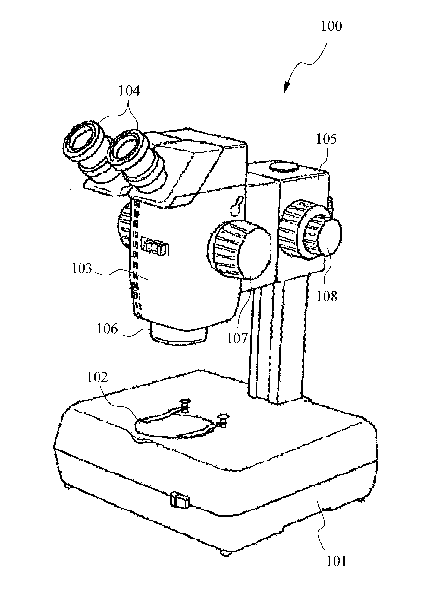
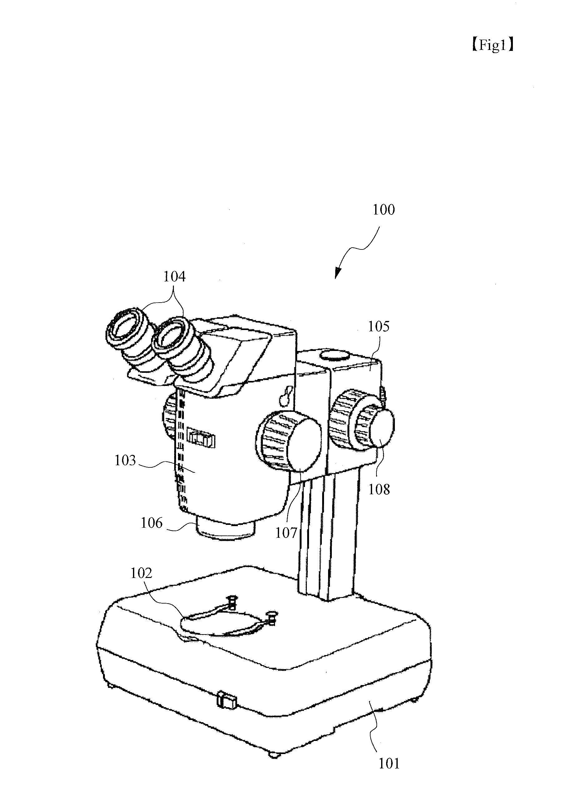
[0031]Hereinafter, preferred embodiments of the present invention will be described with reference to the drawings. In a first embodiment, a case of dividing light exited from an objective lens into two optical paths will be described. First, a configuration of a parallel stereoscopic microscope will be described using FIG. 1. A parallel stereoscopic microscope 100 is a microscope apparatus with a single-objective binocular configuration and includes: a base unit (illumination unit) 101 including a transmitted illumination apparatus; a variable power lens barrel 103 provided with an objective lens and an eyepiece and including variable power lens groups (variable power optical systems) inside; and a focusing apparatus 105. A sample platform 102 embedded with a transparent member is provided on the upper surface of the base unit 101. The objective lens is attached to an objective lens attachment unit 106 provided below the variable power lens barrel 103. In the objective lens attachm...

modified example 1 of first embodiment

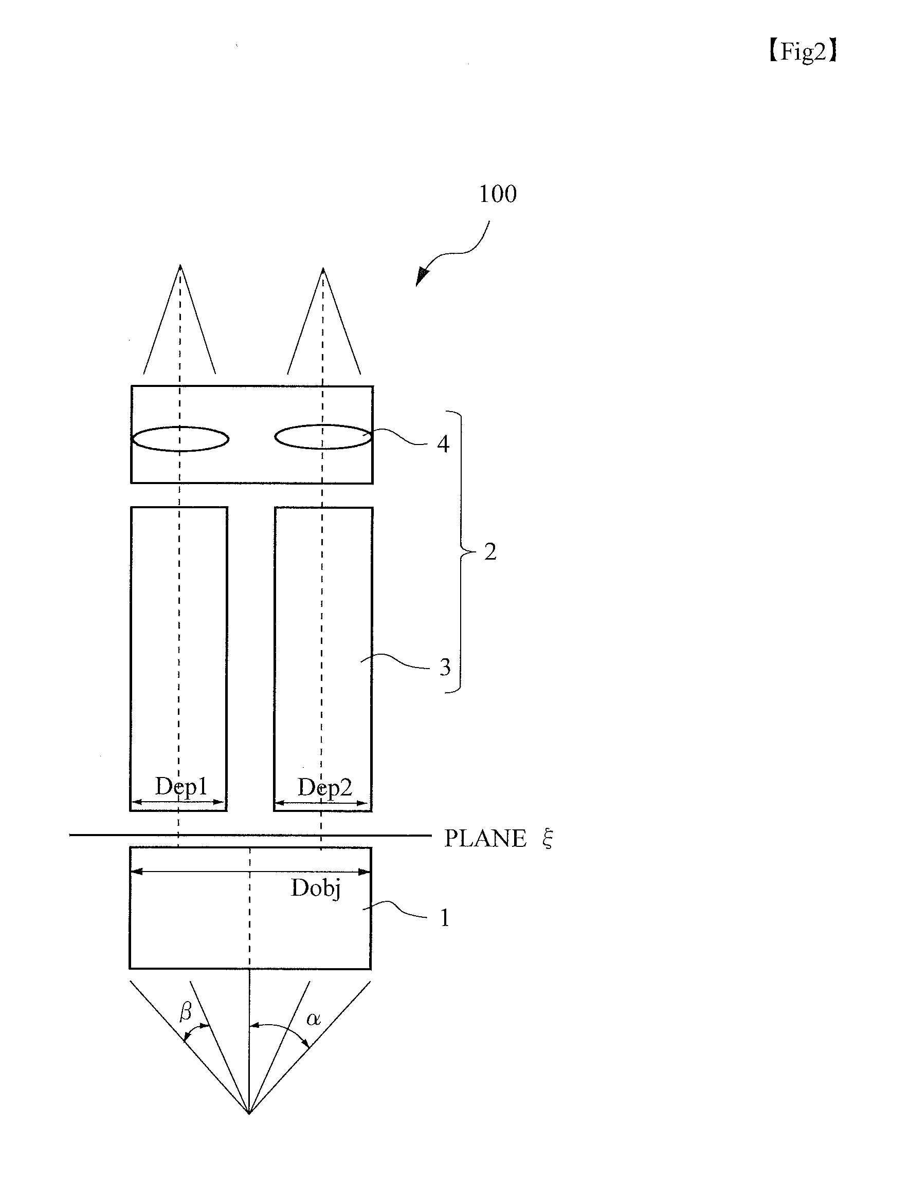
[0045]Although a case of symmetrically arranging the two observation optical systems 2 (variable power lens groups 3) in the X-axis direction of FIG. 4A relative to the optical axis of the objective lens 1 has been described in the above description, the entire variable power lens barrel 103 can be moved relative to the optical axis so that the axial luminous flux diameter Dobj of the objective lens 1 completely includes the entrance pupil of one of the two observation optical systems 2 as shown in FIG. 6 to increase the numerical aperture of at least the optical path of one side compared to the numerical aperture of the conventional parallel stereoscopic microscope apparatus in which the numerical aperture is limited to the distance between the optical axes. Particularly, if the axial luminous flux diameter Dobj of the objective lens 1 is designed to be able to include any one of the entrance pupils of the left and right optical paths (entrance pupil indicated by Dept or entrance p...

modified example 2 of first embodiment

[0046]In recent years, demand for a stereoscopic microscope apparatus capable of observing a wide variable power range by one apparatus is increasing along with the diversification of applications. Particularly, there is a strong demand for the enlargement to the low-power range that allows viewing the entire image of a small animal or the like. FIG. 7 shows optical path diagrams of the objective lens 1 and the variable power lens group 3 of one side, and configurations in which the variable power lens group 3 in two different states of magnification is set to the same objective lens 1 are arranged above and below. FIG. 7(a) shows a low-power end state, and FIG. 7(b) shows a high-power end state. As is clear from FIG. 7, the position of the ray passing through the objective lens 1 is totally different during low-power and during high-power of the variable power lens group 3.

[0047]The magnification of the observation optical system 2 can be calculated by dividing a value f zoom, whic...


PUM


Abstract

A microscope apparatus configured to enlarge entrance pupils while maintaining the rotational symmetry of optical systems of a plurality of optical paths after ejection of light from an objective lens to bring out the performance of the objective lens. A microscope apparatus includes an objective lens having a function of collecting light from the object; and optical paths in which all lens groups are rotational symmetric systems and through which light exited from the objective lens passes, wherein when a sum of maximum diameters of entrance pupils of optical systems forming any two of the optical paths is set as ΣDi, and an axial luminous flux diameter determined from a maximum aperture angle α and a focal distance f of the objective lens is set as Dobj, a condition of the following expression is satisfied, ΣDi>Dobj where Dobj=2·f·sin α.

Description

TECHNICAL FIELD[0001]The present invention relates to a microscope apparatus.BACKGROUND ART[0002]A stereoscopic microscope as an example of a microscope apparatus can stereoscopically observe an object with protrusions and recesses as if the object is viewed by both eyes. Therefore, a distance relationship between a tool, such as tweezers, and an object can be easily recognized in an operation with the microscope. Thus, the stereoscopic microscope is particularly effective in a field that requires precise procedures, such as precision machinery industry and anatomy or surgery of living organisms. In such a stereoscopic microscope, an optical system that guides the luminous flux entering left and right eyes is at least partially separated to cause the optical axes to intersect over the surface of the object to obtain a parallax for stereoscopically observing the object. Enlarged images of the object viewed from different directions are created, and the images are observed through an ...

Claims


Application Information

Patent Timeline
Patent Type & Authority Applications(United States)
IPC IPC(8): G02B21/22
CPCG02B21/22
Inventor MIZUTA, MASAHIRO
Owner NIKON CORP
Why Eureka
Try Eureka