Method for the operation of a transmission device

a transmission device and transmission device technology, applied in mechanical equipment, transportation and packaging, gearing, etc., can solve the problems of insufficient efficiency of the operation of the transmission device made with at least one interlocking shift element and designed as an automatic transmission, and the inability to carry out shifts with interlocking shift elements without interruption of traction force, and achieve high level of shifting comfort

Active Publication Date: 2011-10-27
ZF FRIEDRICHSHAFEN AG
View PDF5 Cites 14 Cited by
  • Summary
  • Abstract
  • Description
  • Claims
  • Application Information

AI Technical Summary

Benefits of technology

[0007]Accordingly, the purpose of the present invention is to provide a method for the operation of a transmission device, by means of which shifts in transmission devices involving at least one interlocking shift element can be carried out with a high level of shifting comfort, inexpensively, and without the need for additional structural fitting space of a transmission device, within predefined shifting times and preferably without traction force interruption.

Problems solved by technology

In a manner known per se, since such transmission devices can only be operated with insufficient efficiencies because of drag losses that occur in the area of open frictional shift elements, certain frictional shift elements are replaced by interlocking shift elements.
Disadvantageously, compared with frictional shift elements interlocking shift elements with or without additional practical synchronization means can only be shifted comfortably when the speed differences are very small, i.e. close to their synchronization speed, so that the operation of a transmission device made with at least one interlocking shift element and designed as an automatic transmission is impaired to an undesired extent, at least when carrying out certain shifts in which an interlocking shift element is involved.
Furthermore, in the area of an interlocking shift element no load transfer of the type that occurs with a frictional shift element is possible before reaching the closed operating condition, so shifts with interlocking shift elements cannot be carried out without interruption of the traction force.
However, additional design measures for synchronizing interlocking shift elements of transmission devices in order to enable shifts to be carried out without traction force interruption within an acceptable shifting time and with a high level of shifting comfort, increase to an undesirable extent both the manufacturing costs of the transmission devices and the structural fitting space that they occupy.

Method used


Image

  • Method for the operation of a transmission device
  • Method for the operation of a transmission device
  • Method for the operation of a transmission device

Examples


Embodiment Construction

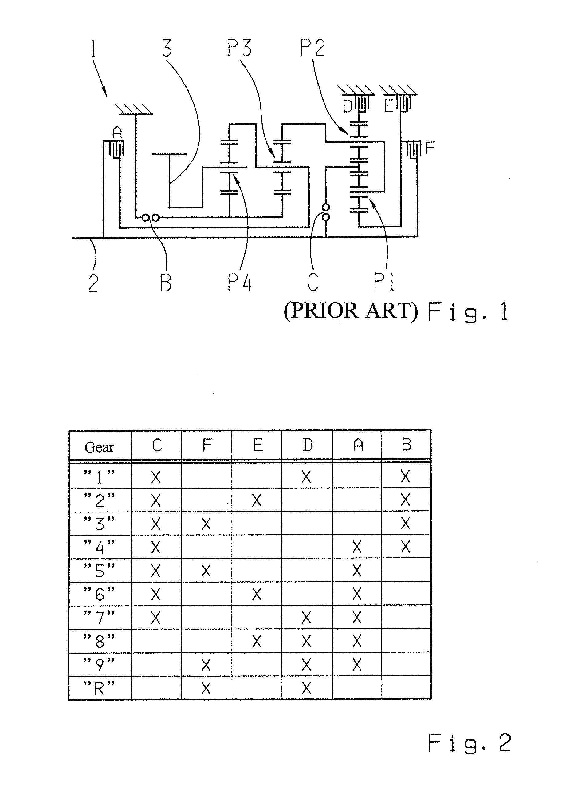
[0027]FIG. 1 shows a gear layout of a transmission device 1 or multi-step transmission, basically known from the unpublished German Patent Application DE 10 2008 000 429.4 by the present applicant. The transmission device comprises a drive input shaft 2 and a drive output shaft 3, the latter, when in its condition mounted in a vehicle, being connected to a drive output of the vehicle, whereas the driveshaft 2 is actively connected to a drive machine.

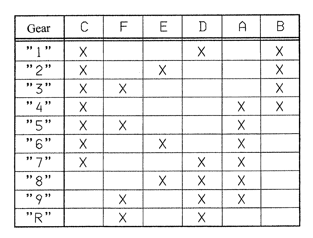
[0028]Moreover, the transmission device 1 comprises four planetary gearsets P1 to P4, such that the first and second planetary gearsets P1, P2, which are preferably designed as minus planetary gearsets, form a shiftable upstream gearset whereas the third and fourth planetary gearsets P3, P4 constitute the main gearset. In addition the transmission device 1 comprises six shift elements A to F of which the shift elements B, D and E are brakes and the shift elements A, C and F are designed as shift clutches.

[0029]With the shift elements A t...


PUM


Abstract

A method is described for the operation of a transmission device (1) with a plurality of frictional shift elements (A, D, E, F) and at least one interlocking shift element (B, C) for obtaining various gear ratios. When a command is received for a gearshift during which the interlocking shift element (C) has to be changed from an open to a closed operating condition, the interlocking shift element (C) is at least approximately synchronized by increasing the transmission capacity of at least one frictional shift element (A) which does not have to be engaged in the force flow either to obtain the gear ratio that is to be disengaged or to obtain the gear ratio that is to be engaged.

Description

[0001]This application is a National Stage completion of PCT / EP2010 / 050341 filed Jan. 13, 2010, which claims priority from German patent application serial no. 10 2009 000 253.7 filed Jan. 15, 2009.FIELD OF THE INVENTION[0002]The invention concerns a method for operating a transmission device.BACKGROUND OF THE INVENTION[0003]Transmission devices known from practice and designed as automatic transmissions are constructed with shift elements for producing various gear ratios, by means of which a respective applied torque can be transmitted by friction. When the engagement of a defined gear ratio is called for, in each case one or more of the frictional shift elements is disengaged from the force flow of the transmission device, while at least one or more further frictional shift elements are engaged in the force flow of the transmission device in order to produce the gear ratio required. During the process of engaging a frictional shift element no special synchronization measures are ...

Claims


Application Information

Patent Timeline
Patent Type & Authority Applications(United States)
IPC IPC(8): F16H59/30
CPCF16H61/0403Y10T477/693F16H2200/2064F16H3/66F16H2003/442F16H2003/445F16H2200/006F16H2200/2012F16H2200/2046F16H2306/44F16H2306/46Y10T477/68F16H2061/205F16H2200/2094Y10T477/693635F16H2061/0407B60W10/00B60W10/08F16H3/00F16H61/00F16H61/04
Inventor ARNOLD, JORGSTEINHAUSER, KLAUSHERBETH, VALENTINEPOPP, CHRISTIANSCHMIDT, THILOZIEMER, PETERDIOSI, GABORMARGRAF, CHRISTOPH
Owner ZF FRIEDRICHSHAFEN AG
Why Eureka
Try Eureka