
Biodegradable Stent Having Non-Biodegradable End Portions and Mechanisms for Increased Stent Hoop Strength

a biodegradable, end portion technology, applied in the field of endoluminal prosthesis, can solve the problems of re-narrowing of the vessel lumen, stent recoiling after the stent, inflammation at the implant site and restnosis, etc., and achieve the effect of increasing the radial strength of the hybrid sten

Active Publication Date: 2011-10-27
MEDTRONIC VASCULAR INC
View PDF9 Cites 127 Cited by
  • Summary
  • Abstract
  • Description
  • Claims
  • Application Information

AI Technical Summary

Benefits of technology

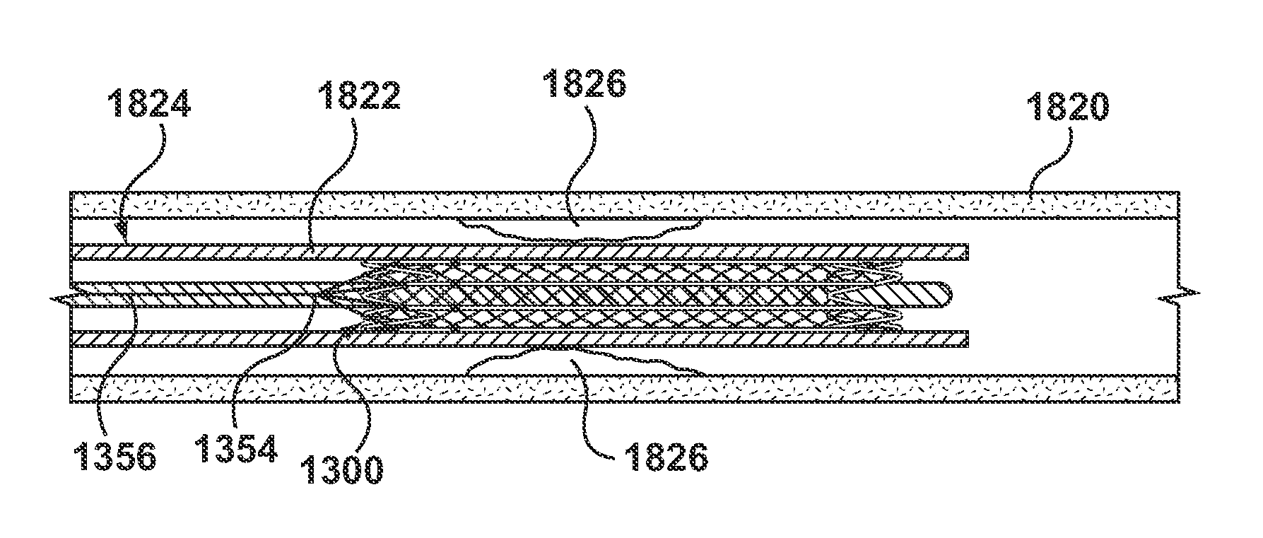
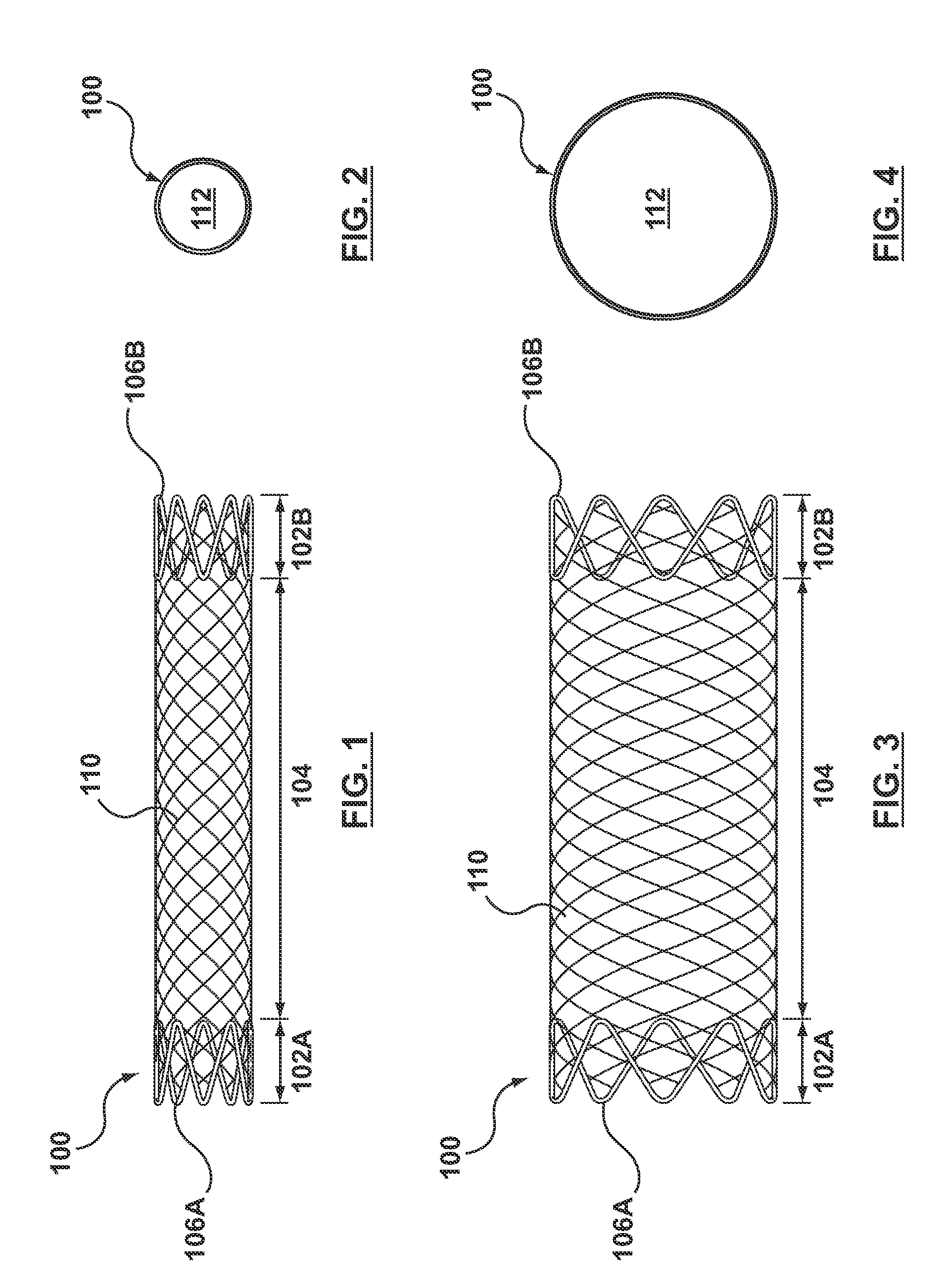
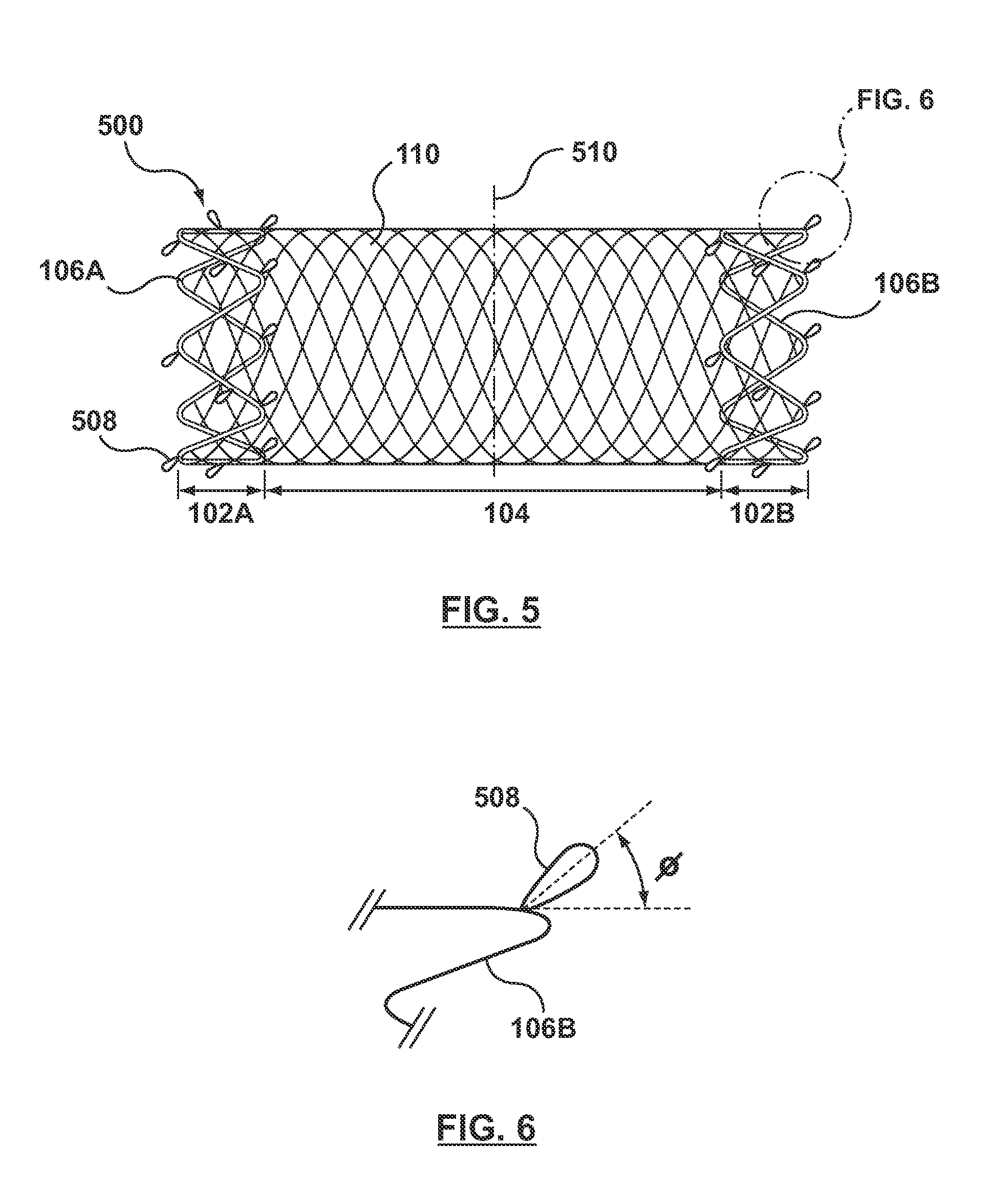
[0007]Embodiments hereof relate to a hybrid stent prosthesis including a biodegradable tubular body, a first non-biodegradable self-expanding ring coupled to a proximal end of the biodegradable body, and a second non-biodegradable self-expanding ring coupled to a distal end of the biodegradable body. The hybrid stent includes a mechanism for longitudinally compressing the tubular body and / or maintaining the tubular body in a longitudinally compressed configuration to increase the radial strength of the hybrid stent.

Problems solved by technology

Permanent stents, over time, may cause irritation to the surrounding tissue resulting in inflammation at the implant site and restenosis, or re-narrowing of the vessel lumen.
Further, if an additional interventional procedure is ever warranted, a previously permanently implanted stent may make it more difficult to perform the subsequent procedure.
The limitations in mechanical strength of the bioabsorbable stents can result in stent recoil after the stent has been inserted.
This makes stent delivery more difficult and can cause a reduction in the area of flow through the lumen.
A larger strut area also increases the level of injury to the vessel wall and this may lead to higher rates of restenosis i.e. re-occlusion of the vessel.
Thus, current totally bioabsorbable stents lack the mechanical properties to sustain vessel lumen size.

Method used


Image

  • Biodegradable Stent Having Non-Biodegradable End Portions and Mechanisms for Increased Stent Hoop Strength
  • Biodegradable Stent Having Non-Biodegradable End Portions and Mechanisms for Increased Stent Hoop Strength
  • Biodegradable Stent Having Non-Biodegradable End Portions and Mechanisms for Increased Stent Hoop Strength

Examples


Embodiment Construction

[0028]Specific embodiments of the present invention are now described with reference to the figures, wherein like reference numbers indicate identical or functionally similar elements. The terms “distal” and “proximal” are used in the following description with respect to a position or direction relative to the treating clinician. “Distal” or “distally” are a position distant from or in a direction away from the clinician. “Proximal” and “proximally” are a position near or in a direction toward the clinician. The terms “biodegradable” and “bioabsorbable” are used in the following description with respect to a property of a material. “Biodegradable” is a material that is capable of being decomposed or broken down in vivo and subsequently excreted. “Bioabsorbable” is a material that is capable of being decomposed or broken down in vivo and subsequently resorbed. Both biodegradable and bioabsorbable materials are suitable for purposes of this application and thus for simplicity, unless...


PUM

PropertyMeasurementUnit
Angleaaaaaaaaaa
Forceaaaaaaaaaa
Angleaaaaaaaaaa

Abstract

A hybrid stent prosthesis including a biodegradable tubular body, a first non-biodegradable self-expanding ring coupled to a proximal end of the biodegradable body, and a second non-biodegradable self-expanding ring coupled to a distal end of the biodegradable body. The hybrid stent includes a mechanism for longitudinally compressing the tubular body to increase the radial or hoop strength thereof. The longitudinally compressing mechanism may be protruding elements coupled to and extending radially outward from the hybrid stent or elastomeric compression bands or tethers extending between the non-biodegradable rings. The compression bands may be pre-connected to both non-biodegradable rings prior to stent delivery, or may be connected to one non-biodegradable ring prior to insertion and connected to the other non-biodegradable ring in situ.

Description

FIELD OF THE INVENTION[0001]The invention relates generally to endoluminal prostheses for placement in a body lumen, and more particularly to a stent prosthesis having a biodegradable body.BACKGROUND OF THE INVENTION[0002]A wide assortment of endoluminal prostheses have been developed, each providing a uniquely beneficial structure to modify the mechanics of a targeted lumen wall within a body lumen. As used herein, “endoluminal prosthesis” is intended to cover a medical device that is adapted for temporary or permanent implantation within a body lumen, including both naturally occurring and artificially made lumens. For example, stent prostheses are known for implantation within body lumens to provide artificial radial support to the wall tissue, which forms the various lumens within the body, and often more specifically, for implantation within the blood vessels of the body. A stent may provide long-term support for damaged or traumatized wall tissues of the lumen or may be implan...

Claims


Application Information

Patent Timeline
IPC IPC(8): A61F2/84A61F2/82A61F2/86A61F2/90
CPCA61F2/07A61F2/852A61F2/86A61F2/90A61F2002/825A61F2220/0016A61F2210/0004A61F2250/0031A61F2250/0063A61F2230/0054A61F2002/8483
Inventor BERGLUNG, JOSEPHPETERSON, JUSTIN
Owner MEDTRONIC VASCULAR INC
Learn More