
Missile Secure-Release Mechanism Having Wheel Lock Detent

a secure release and missile technology, applied in the direction of rocket launchers, weapons, weapons, etc., can solve the problems of the most complicated detent/retention system, the detent is not reusable, and the release force is poorly controlled

Inactive Publication Date: 2011-11-03
UNITED STATES OF AMERICA THE AS REPRESENTED BY THE SEC OF THE ARMY
View PDF9 Cites 12 Cited by
  • Summary
  • Abstract
  • Description
  • Claims
  • Application Information

AI Technical Summary

Benefits of technology

The present invention is able to retain the load along the missile's axis and provides a blast-enabled detent release of the missile from a launch rail while greatly reducing the energy input into the launcher and the airframe of an aircraft.
Upon firing the missile, the exhaust blast from the missile motor hits the trigger, causing the trigger to rotate counter-clockwise out of the propellant plume. This rotational motion is transferred to lateral motion in the connecting rod by the action of the cam surface on the trigger. The connecting rod pulls the lock backward out of the wheel, allowing the wheel to rotate freely, thus releasing the missile to travel freely down the launch rail. When the connecting rod is pulled back, the lock link is disengaged from the secure-release wheel thereby allowing the microswitch pin to contact the microswitch. When the pin-microswitch connection is made, launcher electronics are able to determine an unlatched state.
The present invention may also act as a spring-override detent. The missile may push the secure-release wheel forward off of the wheel lock should any event occur such that the trigger fails to release the secure-release wheel. The secure-release wheel is mounted upon a wheel slider connected to release springs such that when the missile pushes upon the secure-release wheel, the wheel slider moves forward and away from the wheel lock, compressing two compression springs, and allowing the secure-release wheel to rotate.
Also, the trigger of the trigger assembly is able to rotate 180 degrees such that the trigger can be pointed up. This allows the secure-release mechanism to be placed flat on a horizontal surface for storage while protecting the trigger from damage.

Problems solved by technology

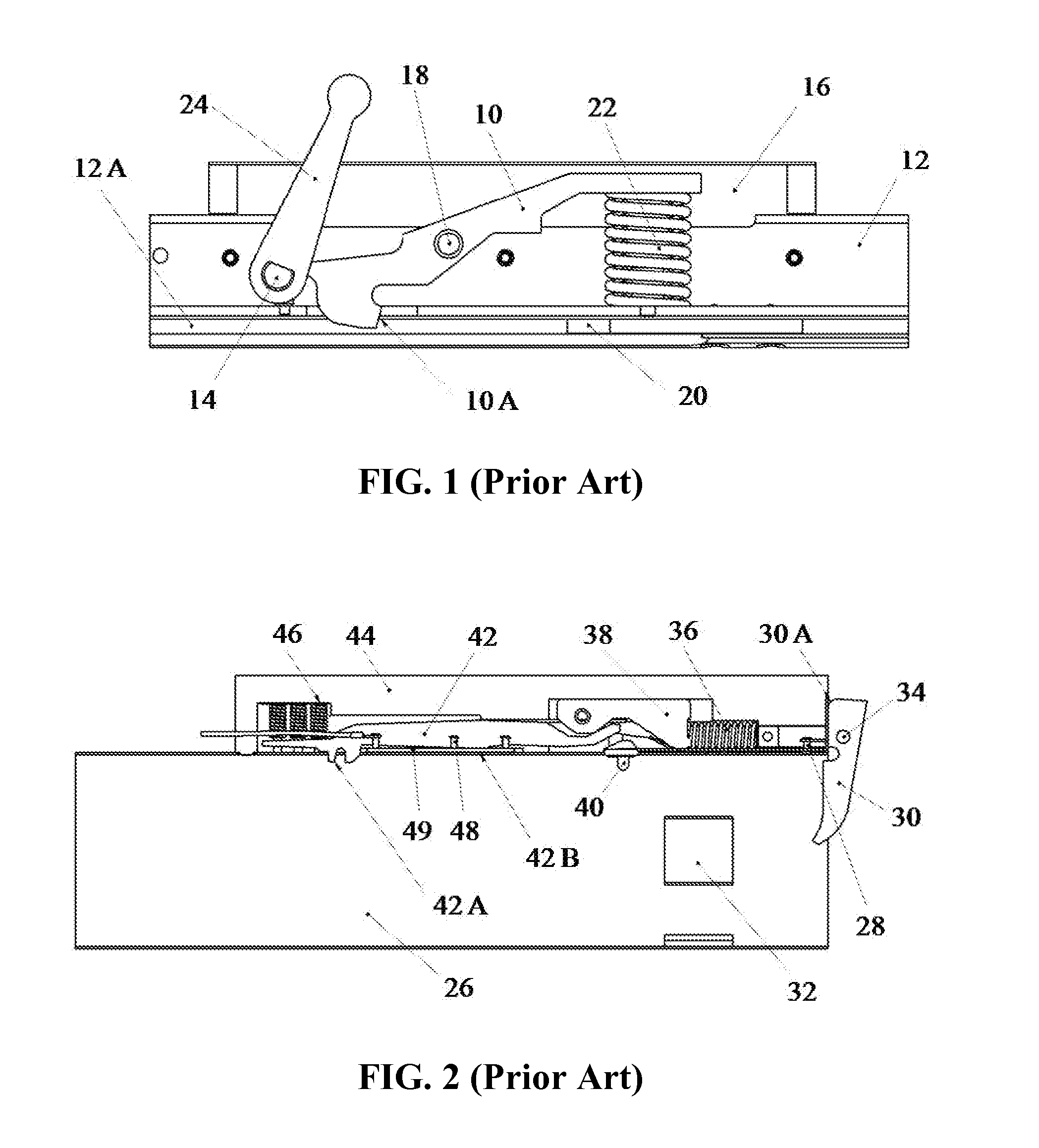
Release force is well controlled in this detent mechanism, but the detent is not reusable.
The release force is poorly controlled, but the launcher may be used multiple times.
This is the most complicated detent / retention system.
The hot gases also exit the rocket nozzle and put an unbalanced gas pressure on the blast paddle 30.

Method used


Image

  • Missile Secure-Release Mechanism Having Wheel Lock Detent
  • Missile Secure-Release Mechanism Having Wheel Lock Detent
  • Missile Secure-Release Mechanism Having Wheel Lock Detent

Examples


Embodiment Construction

Reference is now made to the drawings wherein like numbers represent like parts in each of the several figures.

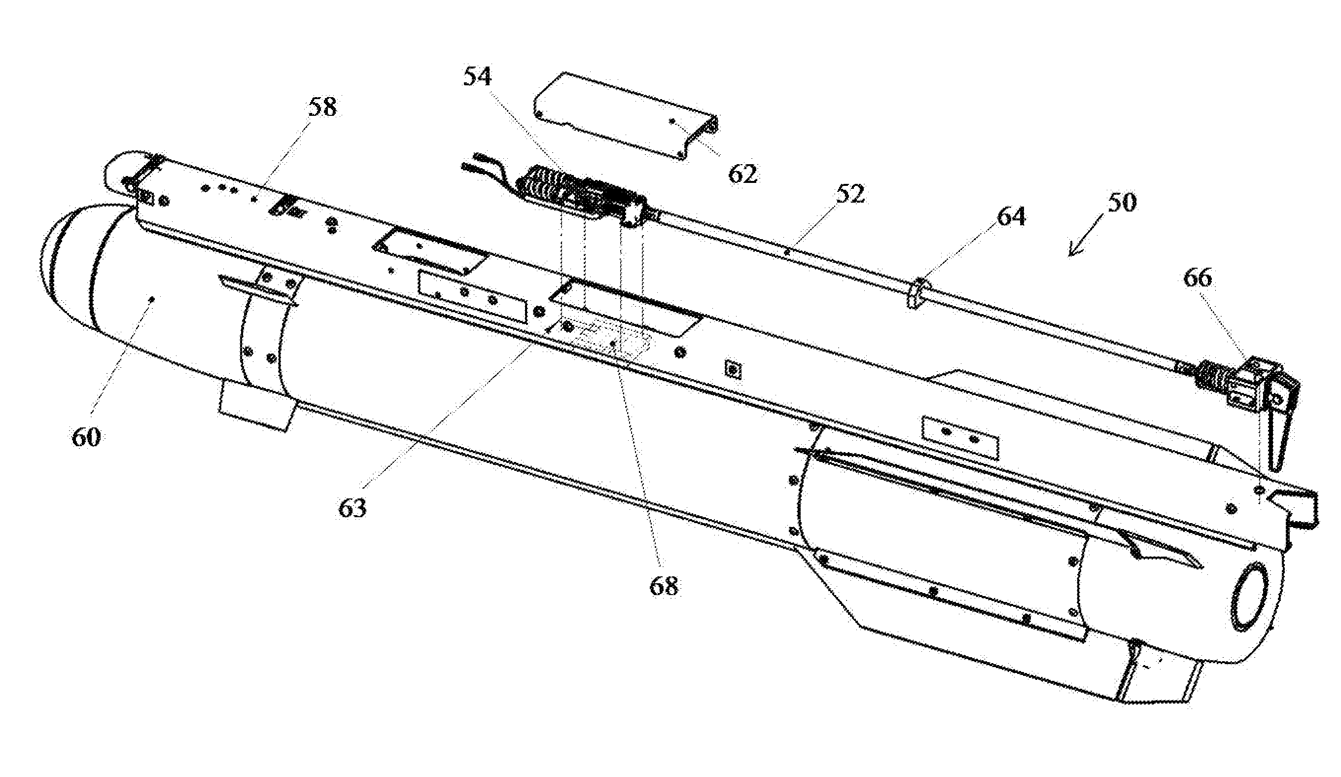
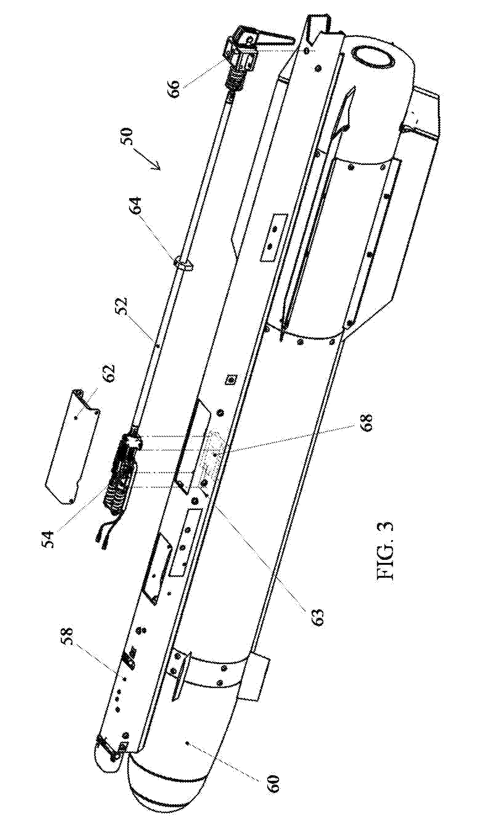
In FIG. 3, a securing-releasing mechanism 50 is provided with a trigger assembly 66 and a wheel assembly 54 which are connected by connecting rod 52. The trigger assembly 66 and the wheel assembly 54 are secured to the launch rail 58. The connecting rod 52 is held in position above the launch rail 58 by lubricated rod guide 64. The wheel assembly 54 is protected from the environment by a cover 62. When missile 60 is loaded onto the rail 58, the wheel assembly 54 securely retains the missile 60 on the rail 58 until the missile is launched.

In FIG. 4, a secure-release wheel 70 is mounted to wheel slider 76 by wheel pivot pin 74. The slider pin 90 is inserted into the wheel slider 76 such that the rotational position of the wheel 70 is limited in either rotational direction by slider pin 90. The wheel slider 76 is inserted into the forward end of the wheel housing 72.

Safety rel...


PUM


Abstract

The invention efficiently and effectively secures and releases a rail-launched missile. An asymmetrical secure-release wheel (70) is defined by several surfaces which extend radially outward from a pivot hole (70K). The surfaces include a wheel unlatch surface (70H), a wheel notch stop surface (70D), a wheel detent surface (70G), a clockwise stop surface (70C) and a counterclockwise stop surface (70B). The wheel (70) is rotatable within a wheel housing (72). When a missile is loaded onto the launch rail, the middle shoe of the missile engages the detent surface (70G) of the wheel. During missile launch, the plume of the missile moves a trigger (110) which pulls a connecting rod (52) aft which results in a wheel lock (78) being disengaged from the detent surface (70G). A microswitch (56) provides a signal indicating whether the wheel (70) is in a latched or unlatched state.

Description

BACKGROUND OF THE INVENTION1. Field of the InventionThe present invention pertains to mechanisms and systems for retaining and releasing a missile on a rail launch system.2. Discussion of the BackgroundIn order to assure accuracy of a missile launcher, it is desirable for a missile launcher to provide a smooth release and induce a minimum of impulse back into the launching platform of an air launched missile. Prior to the fielding of the Army HYDRA 70 Lightweight Launchers, M260 and M261, for the 2.75 Inch Rocket System, the retention mechanisms for tactical launchers fell into three categories.The first approach was called a material failure detent. For systems that employ this approach, the munition is restrained by a material component that was designed to fail (i.e. break) when the launch motor thrust became higher than the material strength of the detent. Release force is well controlled in this detent mechanism, but the detent is not reusable. The TOW Missile System is an exam...

Claims


Application Information

Patent Timeline
IPC IPC(8): F41F3/052
CPCF41F3/052F41F3/0406
Inventor HAINZE, SEAN A.DAVIS, DONALD E.
Owner UNITED STATES OF AMERICA THE AS REPRESENTED BY THE SEC OF THE ARMY
Features
  • Generate Ideas
  • Intellectual Property
  • Life Sciences
  • Materials
  • Tech Scout
  • Unparalleled Data Quality
  • Higher Quality Content
  • 60% Fewer Hallucinations
Learn More