Track-guided vehicle wheel truck

a technology of vehicle wheels and wheels, which is applied in the direction of wheel axle self-adjustment, transportation and packaging, rope railways, etc., can solve the problems of easy wear and deterioration of achieve the reduction of the contact pressure between the guide wheel and the guide rail, the effect of reducing the cornering force and reducing the working force directed toward the guide rail

Active Publication Date: 2011-11-03
MITSUBISHI HEAVY IND ENG LTD
View PDF11 Cites 19 Cited by
  • Summary
  • Abstract
  • Description
  • Claims
  • Application Information

AI Technical Summary

Benefits of technology

[0012]The following effects can be obtained according to the present invention. A track-guided vehicle wheel truck according to the present invention includes: a pair of running wheels respectively connected to both ends of a steering axle by a kingpin; a guide wheel guided along a guide which is provided on a running track; and a guide frame to which the guide wheel is mounted, wherein the guide frame can turn relative to the steering axle. Such a track-guided vehicle comprises: a tie rod being arranged along a vehicle width direction on a center side of a vehicle front and rear direction relative to the steering axle, and being capable of interlocking the pair of running wheels with each other; a connecting rod being arranged on a vehicle end side of the vehicle front and rear direction relative to the steering axle, and being capable of steering one of the pair of running wheels; a first steering arm arranged along the vehicle front and rear direction, and mounted to one of the kingpins of the pair of running wheels; a second steering arm arranged along the vehicle front and rear direction, and mounted to the other of the kingpins of the pair of running wheels; an axle bracket provided along the vehicle front and rear direction so as to straddle the steering axle in a center of the vehicle width direction of the steering axle; a support shaft provided on the axle bracket such that position thereof can be adjusted in the vehicle front and rear direction so as to straddle the steering axle relative to the axle bracket; and a link lever arranged along the vehicle front and rear direction; wherein both end parts of the tie rod are rotatably mounted respectively to center-side end parts of the first steering arm and the second steering arm; wherein both end parts of the connecting rod are rotatably mounted respectively to a vehicle end-side end part of the first steering arm and a vehicle end-side end part of the link lever, wherein an intermediate part of the link lever is rotatably mounted to the guide frame, wherein a long hole is provided in a center-side end part of the link lever so as to extend in the vehicle front and rear direction; and wherein the long hole and the support shaft are rotatably engaged with each other at a given position.
[0013]Therefore, the support shaft provided as the rotation center of the link lever, is movable in the vehicle front and rear direction so as to straddle the steering axle.
[0014]Here, in a case in which the rotation center of the link lever is positioned on the vehicle end side of the steering axle, when the guide wheel and the guide frame are turned along a curved guide rail, the intermediate part of the link lever is rotatably mounted to the guide frame, so that the link lever rotates around the support shaft in the center-side end part. The vehicle end-side end part of the link lever, rotates in a larger circle than the intermediate part of the link lever, corresponding to the ratio of the distance between the vehicle end-side end part of the link lever and the support shaft in the center-side end part to the distance between the intermediate part of the link lever and the support shaft in the center-side end part. At this time, the vehicle end-side end part of the link lever is moved largely in the same direction as the turning of the guide frame. The connecting rod is thereby moved, so that the first steering arm is also moved. As a result, one of the pair of running wheels is steered to assume a slip angle in an oversteered state which is larger than the turning angle of the guide frame. In addition, the tie rod is moved when one of the pair of running wheels is steered, so that the second steering arm is moved. As a result, the other of the pair of running wheels is steered to assume a slip angle in an oversteered state.
[0015]On the other hand, in a case in which the rotation center of the link lever is positioned on the center side of the steering axle, when the guide wheel and the guide frame are turned, the vehicle end-side end part of the link lever rotates in a larger circle than the intermediate part of the link lever, corresponding to t

Problems solved by technology

As a result, there occurs a problem in that wear and deterior

Method used


Image

  • Track-guided vehicle wheel truck
  • Track-guided vehicle wheel truck
  • Track-guided vehicle wheel truck

Examples


first embodiment

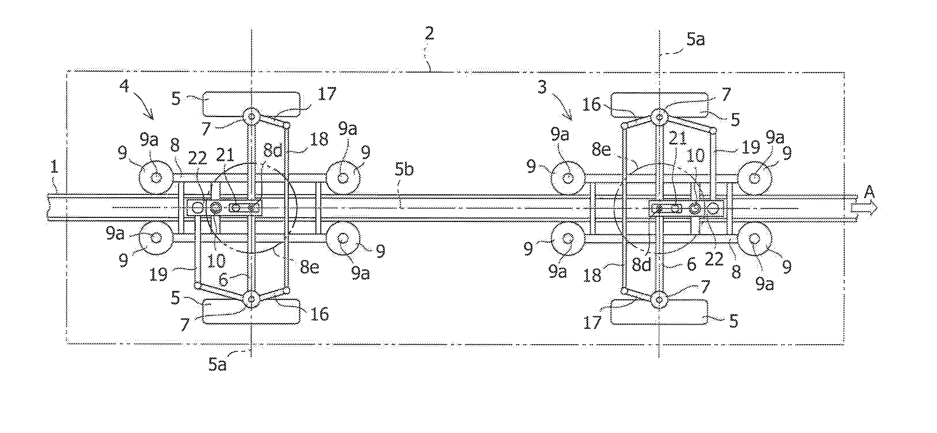
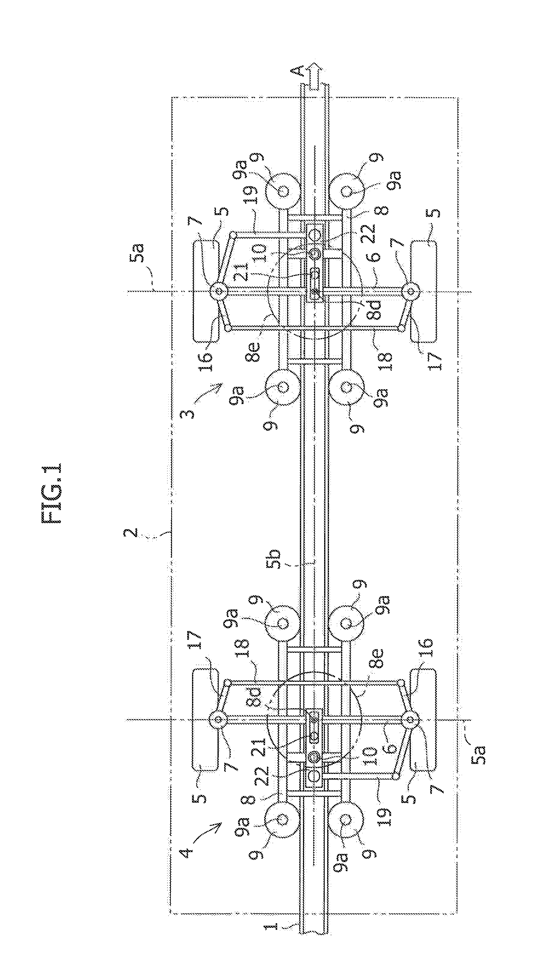
[0028]A vehicle wheel truck according to the first embodiment of the present invention will be described below. Referring to FIG. 1, in a vehicle traveling in the direction indicated by the arrow A, a pair of right and left center guides 1 in the vehicle width direction are arranged along a track path of the vehicle in the middle of the vehicle width direction of the vehicle. The vehicle runs while being guided along the center guide 1. In the vehicle as described above, a front wheel truck 3 and a rear wheel truck 4 are respectively arranged on the front side and the rear side of the vehicle under a vehicle body 2.

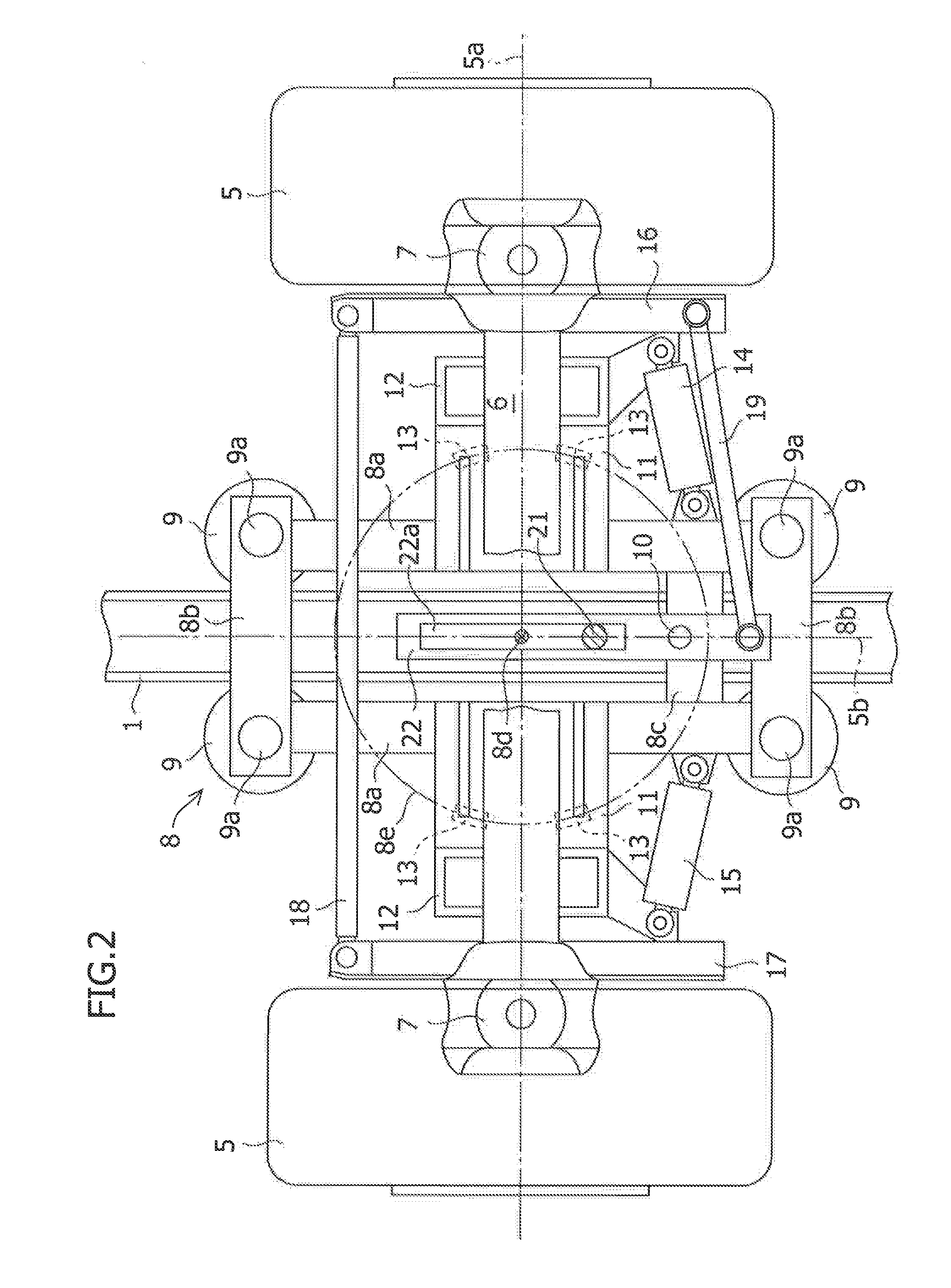
[0029]The structures of the front wheel truck 3 on the front side and the rear wheel truck 4 on the rear side (hereinafter referred to as “wheel trucks 3 and 4”) will now be described by reference to FIGS. 1 to 3. In the wheel trucks 3 and 4, a pair of running wheels 5 is provided. As one example of the running wheel 5, a rubber tire is used mainly in a vehicle such as a ...

second embodiment

[0044]Vehicle wheel trucks according to the second embodiment of the present invention will be described below. The basic features of the vehicle in the second embodiment are the same as those of the vehicle in the first embodiment. The description is given applying the same symbols and names as those in the first embodiment to elements that are essentially the same as those in the first embodiment. Features different from those in the first embodiment will be described below.

[0045]As shown in FIG. 7, a restoration mechanism 31 is arranged along the vehicle front and rear direction in the guide frame 8. The restoration mechanism 31 is provided so as to restore the support shaft 21 to an original neutral position in a straight running state when the support shaft 21 is moved during curve running or the like. As one example of the restoration mechanism 31, a coil spring may be used. Any urging means other than the coil spring may be also used. Furthermore, in the guide frame 8, an act...

third embodiment

[0047]Vehicle wheel trucks according to the third embodiment of the present invention will be described below. The basic features of the vehicle in the third embodiment are the same as those of the vehicle in the second embodiment. The description is given applying the same symbols and names as those in the third embodiment to elements that are essentially the same as those in the second embodiment. Features different from those in the second embodiment will be described below.

[0048]As shown in FIG. 8, in the guide frame 8, a pair of longitudinal beams 8g is arranged at an interval in the vehicle width direction so as to extend in the vehicle front and rear direction. Lateral beams 8h are arranged so as to respectively extend in the vehicle width direction at both end parts of the vehicle front and rear direction of the guide frame 8. The guide wheels 9 are mounted to both end parts of the lateral beam 8h so as to be rotatable around the rotation shaft 9a. Leaf springs 41 are arrang...


PUM


Abstract

A track-guided vehicle wheel truck prevents wear and deterioration of a guide wheel and a guide rail, and ensures running stability while simplifying the structure. In the track-guided vehicle wheel truck, a guide frame 8 to which a guide wheel 9 guided by a guide rail 1 is mounted, can turn relative to a steering axle 6 of a running wheel 5. A support shaft 21 is provided on an axle bracket 20 provided in the steering axle 6 so as to be movable in the vehicle front and rear direction by straddling the steering axle 6. A link lever 22 capable of interlocking the turning of the guide frame 8 and the steering of the running wheel 5 is provided along the vehicle front and rear direction. A vehicle end-side end part of the link lever 22 is rotatably mounted to a connecting rod 19 that enables the steering of the running wheel 5. An intermediate part of the link lever 22 is rotatably mounted to the guide frame 8. A long hole 22a extending in the vehicle front and rear direction is provided in a center-side end part of the link lever 22. The long hole 22a and the support shaft 10 are rotatably engaged with each other at a given position.

Description

TECHNICAL FIELD[0001]The present invention relates to a track-guided vehicle wheel truck (bogie) which runs along a track.BACKGROUND ART[0002]In general, a track-guided vehicle (hereinafter referred to as a “vehicle”), such as a subway car, or a new transportation system vehicle, runs along a track while being guided by a guide rail arranged along the track. In a wheel truck of a conventional vehicle, a running wheel of a rubber tire, or the like, is arranged facing in a fixed direction at all times relative to a guide wheel guided by the guide rail. Therefore, the direction of the running wheel is changed only by following the guide rail. However, when the vehicle moves into a curved guide rail, a large guide wheel working force directed toward the guide rail is applied to the guide wheel due to a force generated by the running wheel traveling straight or a centrifugal force acting on the vehicle. The guide wheel and the guide rail are thereby brought into contact with each other a...

Claims


Application Information

Patent Timeline
IPC IPC(8): B61F5/38
CPCB61B10/04B61B13/00B61F5/38
Inventor KURAHASHI, HIROKIFUJIO, NOBUYUKIKONO, HIROYUKIYANOBU, YUKIHIDEKAWAUCHI, AKIHISAKATAHIRA, KOUSUKE
Owner MITSUBISHI HEAVY IND ENG LTD
Why Eureka
Try Eureka