
Charge control circuit, battery pack, and charge system

a control circuit and battery technology, applied in secondary cells, battery components, battery servicing/maintenance, etc., can solve problems such as and achieve the effect of reducing the deterioration of rechargeable batteries

Active Publication Date: 2011-11-03
PANASONIC CORP
View PDF8 Cites 66 Cited by
  • Summary
  • Abstract
  • Description
  • Claims
  • Application Information

AI Technical Summary

Benefits of technology

[0009]It is an object of the present invention to provide a charge control circuit, a battery pack and a charge system that allow reducing rechargeable battery deterioration during constant current charging by CCCV charging.

Problems solved by technology

This is problematic in that, as a result, the rechargeable battery may deteriorate when constant current charging is carried out, at a same current value, from a state where SOC is close to 0% up to a state close to full charge.

Method used


Image

  • Charge control circuit, battery pack, and charge system
  • Charge control circuit, battery pack, and charge system
  • Charge control circuit, battery pack, and charge system

Examples


Embodiment Construction

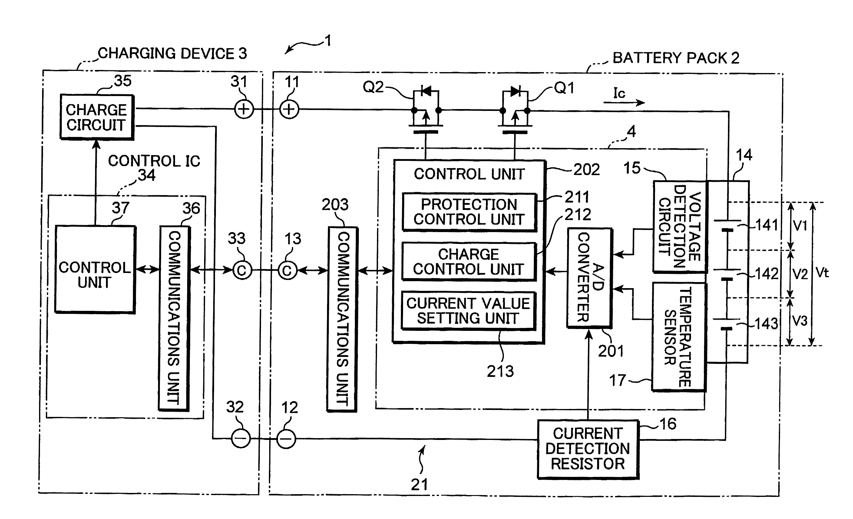
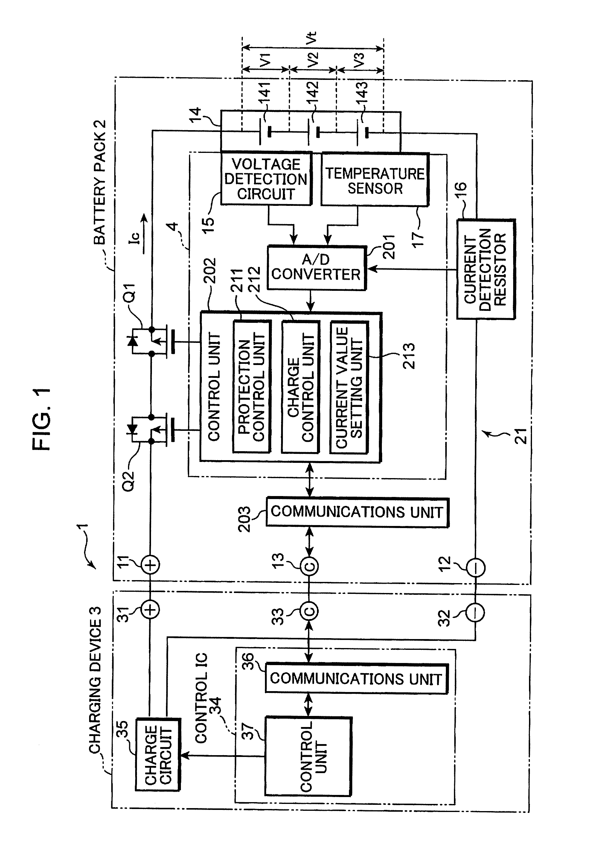
[0018]Embodiments of the present invention are explained below with reference to accompanying drawings. In the drawings, features denoted with the same reference numerals are identical features, and a recurrent explanation thereof will be omitted. FIG. 1 is a block diagram illustrating an example of the configuration of a battery pack and of a charge system that comprise a charge control circuit according to an embodiment of the present invention. A charge system 1 illustrated in FIG. 1 comprises a combination of a battery pack 2 and a charging device 3 (charging unit).

[0019]The charge system 1 may further comprise a load device, not shown, that is supplied with power from the battery pack 2, for instance, an electronic device such as a portable personal computer, a digital camera or a mobile phone, or an electronic device system used in, for instance, a vehicle such as an electric automobile or a hybrid car. In this case, the battery pack 2 is directly charged from the charging dev...


PUM


Abstract

A charge control circuit includes a charge control unit that controls an operation of a charging unit that charges a rechargeable battery; and a voltage detection unit that detects a terminal voltage of the rechargeable battery, wherein when a terminal voltage of the rechargeable battery as detected by the voltage detection unit is lower than a predetermined first threshold-value voltage, being lower than a full-charge voltage which is a terminal voltage of the rechargeable battery in full charge, the charge control unit causes a constant current charging to the rechargeable battery by requesting the charging unit to supply a charging current of a predetermined first current value, causing the charging unit to supply a charging current of the first current value to the rechargeable battery, when the terminal voltage of the rechargeable battery as detected by the voltage detection unit exceeds the first threshold-value voltage but is less than the full charge voltage, the charge control unit causes the constant current charging to the rechargeable battery by requesting the charging unit to supply a charging current of a second current value that is smaller than the first current value, causing the charging unit to supply a charging current of the second current value to the rechargeable battery, and when the terminal voltage of the rechargeable battery as detected by the voltage detection unit is equal to or greater than the full charge voltage, the charge control unit causes a constant voltage charging to be carried out by causing the charging unit to supply the full charge voltage to the rechargeable battery, as a charge voltage.

Description

TECHNICAL FIELD[0001]The present invention relates to a charge control circuit that controls charging of a rechargeable battery, and to a battery pack and to a charge system that are provided with the charge control circuit.BACKGROUND ART[0002]Conventional known ways of charging a rechargeable battery include CCCV (constant current-constant voltage) charging schemes wherein constant current charging, in which charging is carried out at a constant current value, is performed initially, and when the terminal voltage of the rechargeable battery reaches a charge termination voltage set beforehand, there is performed constant voltage charging, in which the battery is charged at a constant charge voltage, through application of the charge termination voltage to the rechargeable battery (for instance, see Patent document 1).[0003]In a CCCV charging scheme, the open-circuit voltage (OCV) at the time of full charge when the SOC (State of Charge) of the rechargeable battery is 100%, i.e. the ...

Claims


Application Information

Patent Timeline
IPC IPC(8): H02J7/04H01M50/574
CPCH01M2/34H01M2/348H01M10/425H01M10/44Y02E60/12H01M10/48H01M10/486H01M2200/10H02J7/0073H01M10/46H02J7/0071Y02E60/10H01M50/581H01M50/574
Inventor NAKATSUJI, TOSHIYUKIMORIMOTO, TSUYOSHI
Owner PANASONIC CORP
Features
  • Generate Ideas
  • Intellectual Property
  • Life Sciences
  • Materials
  • Tech Scout
  • Unparalleled Data Quality
  • Higher Quality Content
  • 60% Fewer Hallucinations
Learn More