
Systems and methods for controlling an inertia of a synchronous condenser

a technology of synchronous condensers and inertia control, which is applied in the direction of motor/generator/converter stoppers, dynamo-electric converter control, and primary cell maintainance/servicing. it can solve the problems of slowing down of synchronous condensers, limited practical and insufficient use of flywheels to increase the h value of synchronous condensers

Inactive Publication Date: 2011-11-03
GENERAL ELECTRIC CO
View PDF5 Cites 3 Cited by
  • Summary
  • Abstract
  • Description
  • Claims
  • Application Information

AI Technical Summary

Benefits of technology

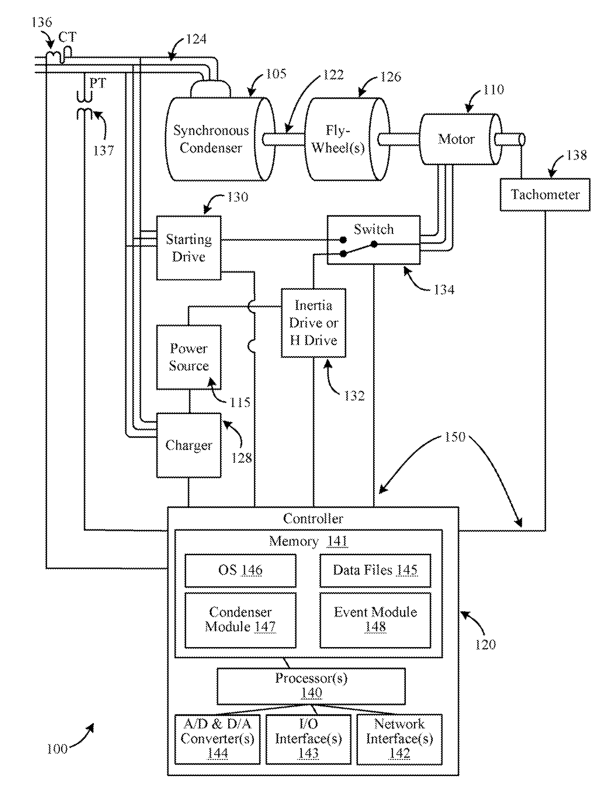
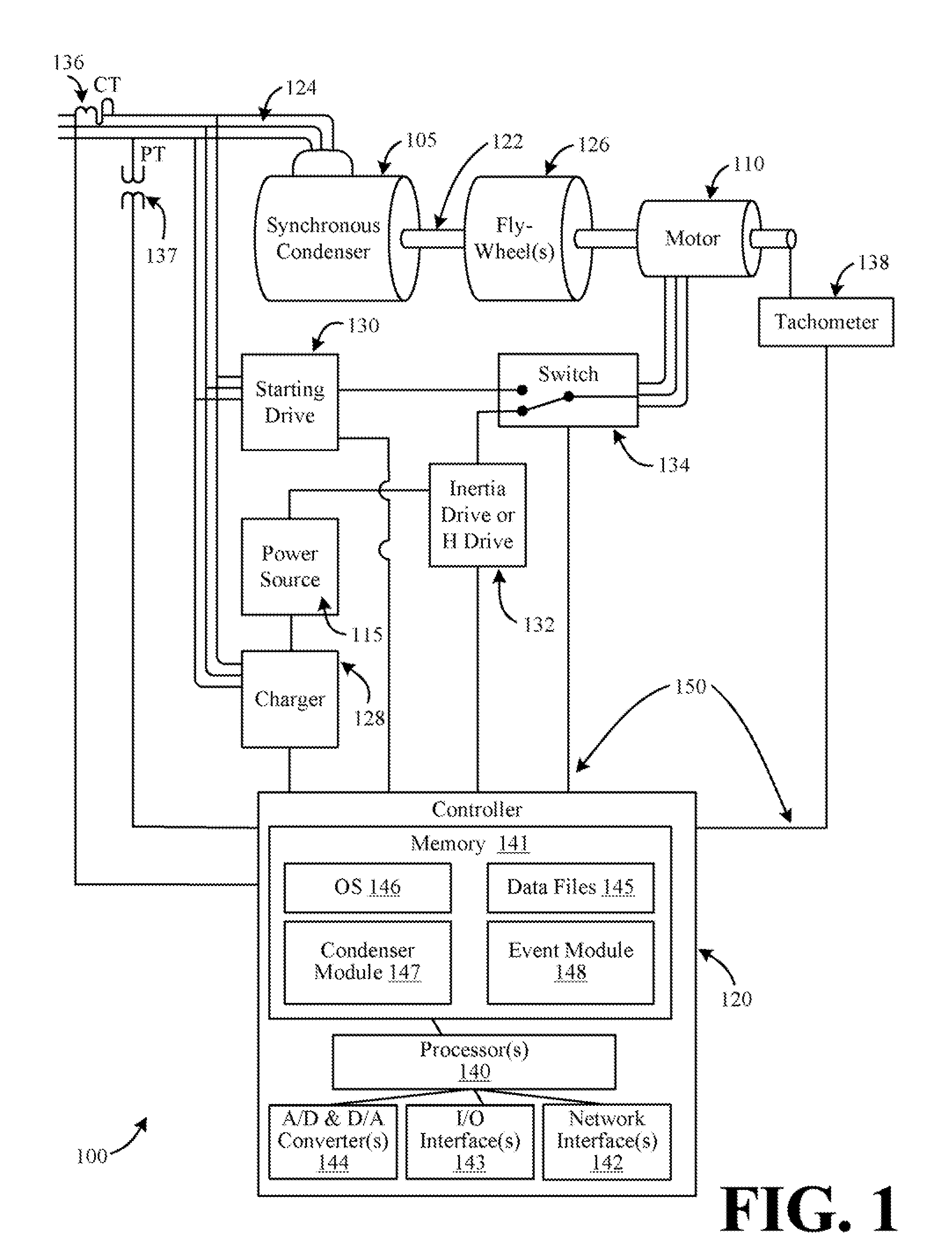
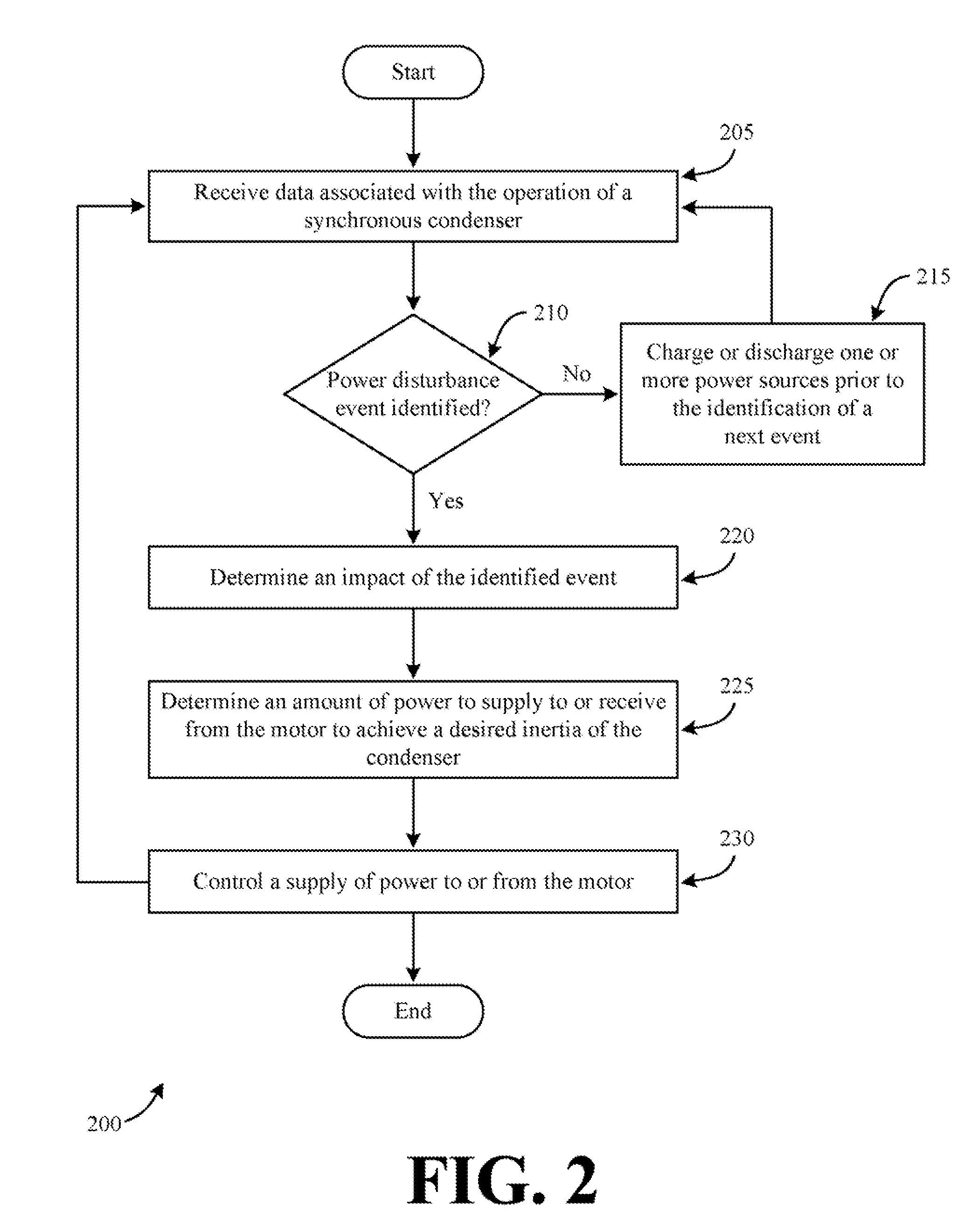
[0004]Some or all of the above needs and/or problems may be addressed by certain embodiments of the invention. Embodiments of the invention may include systems and methods for controlling an inertia of a synchronous condenser. According to one embodiment of the invention, there is disclosed a system for controlling an inertia of a synchronous condenser. The system may include a motor, a bidirectional power source coupled to the motor, and at least one control device. The motor may be configured to alter a rotation of a condenser shaft to obtain a desired inertia of the synchronous condenser during a power disturbance event. The at least one control device may be configured to identify the power disturbance event and determine an amount of power to supply to or receive from the motor to obtain the desired inertia. Additionally, the at least one controller may be configured to control the supply of power from the power source to the motor or from the motor to the power source based upon the determined amount of power.
[0005]According to another embodiment of the invention, there is disclosed a method for controlling an inertia of a synchronous condenser. A motor may be provided that is configured to alter a rotation of a condenser shaft to obtain a desired inerti

Problems solved by technology

For example, a line fault within a power distribution grid will typically cause the synchronous condenser to slow down.
However, there are practical limits to the H value of a synchronous condenser.
Additionally, the use of flywheels is often not sufficient to increase the H value of a synchronous condenser to a desired value to accommodate various power disturbance events.

Method used


Image

  • Systems and methods for controlling an inertia of a synchronous condenser
  • Systems and methods for controlling an inertia of a synchronous condenser
  • Systems and methods for controlling an inertia of a synchronous condenser

Examples


Embodiment Construction

[0011]Illustrative embodiments of the invention now will be described more fully hereinafter with reference to the accompanying drawings, in which some, but not all embodiments of the invention are shown. Indeed, the invention may be embodied in many different forms and should not be construed as limited to the embodiments set forth herein; rather, these embodiments are provided so that this disclosure will satisfy applicable legal requirements. Like numbers refer to like elements throughout.

[0012]Disclosed are systems and methods for controlling an inertia of a synchronous condenser. According to an example embodiment of the invention, a motor may be configured to alter a rotation of a condenser shaft associated with a synchronous condenser. In this regard, a desired inertia of the synchronous condenser may be achieved and / or maintained during a power disturbance event. A wide variety of suitable motors may be utilized as desired in various embodiments of the invention, such as an ...


PUM


Abstract

Systems and methods for controlling an inertia of a synchronous condenser are described. An example system may include a motor, bidirectional power source, and at least one control device. The motor may be configured to alter a rotation of a condenser shaft to obtain a desired inertia of a synchronous condenser during a power disturbance event. The bidirectional power source may be coupled to the motor. The at least one control device may be configured to identify the power disturbance event, determine an amount of power to supply to or receive from the motor to obtain the desired inertia, and control the supply of power from the power source to the motor or from the motor to the power source based upon the determined amount of power.

Description

FIELD OF THE INVENTION[0001]Embodiments of the invention relate generally to synchronous condensers and more specifically to controlling an inertia of a synchronous condenser.BACKGROUND OF THE INVENTION[0002]Synchronous condensers are utilized in a wide variety of applications, such as power generation applications. For power generation applications, synchronous condensers are typically utilized to adjust electrical conditions on a local electric power distribution grid. A synchronous condenser is a specialized motor whose shaft is not attached to anything, but rather spins freely.[0003]During a power disturbance event within a power generating system, the rotation of a synchronous condenser will typically fluctuate from a desired value. For example, a line fault within a power distribution grid will typically cause the synchronous condenser to slow down. These undesired fluctuations are typically greater for synchronous condensers utilized in conjunction with renewable power source...

Claims


Application Information

Patent Timeline
IPC IPC(8): G05F1/12
CPCH02J3/30H02P2101/15Y02E60/16H02P9/105
Inventor MARKEN, PAUL EDWARDWALLACE, DANIEL ROBERT
Owner GENERAL ELECTRIC CO
Learn More