
Automatic register control system with intelligent optical sensor and dry presetting facility

a register control system and optical sensor technology, applied in the field of automatic register control system with intelligent optical sensor and dry presetting facility, can solve the problems of poor color registration, large amount of wasted, and method is not cost effective, and achieve the effect of minimizing printing losses and cost-effectiveness

Inactive Publication Date: 2011-11-03
ECOAXIS SYST PVT LTD
View PDF0 Cites 11 Cited by
  • Summary
  • Abstract
  • Description
  • Claims
  • Application Information

AI Technical Summary

Benefits of technology

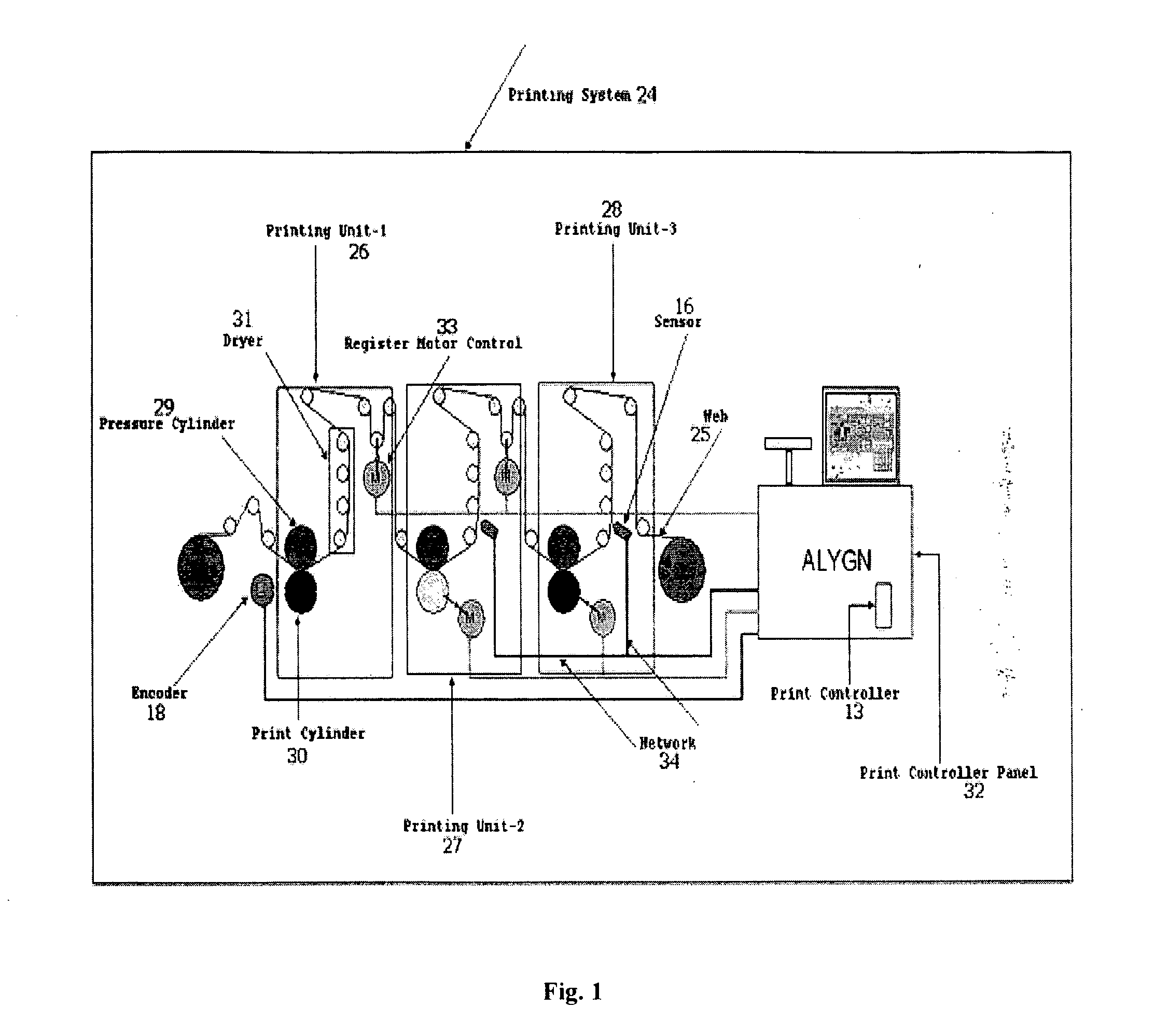
[0020]Accordingly, the primary object of the present invention is to provide a cost-effective multi-utility system for intelligently controlling print misregistration in order to significantly minimize the printing losses.
[0021]In effect thereof, one of the primary objects of the present invention is to provide a precise method for introducing a dry register presetting arrangement among the set of print stations with respect to each other before the start of a print job in order to avoid the wastage of substrate.
[0022]Another essential object of the present invention is to provide a system for achieving print accuracy in high speed printing machines by overcoming the limitation of loss of analogue signal and noise generation during transportation.

Problems solved by technology

In high volume and high quality printing, carried out mostly by rotogravure printing machines, in-line flexographic printing machines or label printing machines, the print quality drastically suffers due to various dynamic conditions resulting in poor color registration, and thus the maintenance of print quality is a major concern in the printing industry.
Primarily, one of the inherent limitations of the prior art is that, in order for a typical register control system to work, it is imperative that the printing machine is made to run at least once.
This leads to large amounts of wastage and hence such a method is not cost effective.
Furthermore, a common problem with the adjustment of the preset is that when there are different print repeats, the web length between the print stations varies accordingly.
If this variation is not addressed appropriately while presetting the printing machine, the system will not be in proper registration.
As a result thereby, the register control system cannot automatically start bringing the print in tight tolerance.
This requires manual intervention by the operator which again generates some additional waste of time and material.
In all such improvements and advancements, it is observed that the arrangements are not effective and accurate for attaining absolute presetting conditions.
Further, regarding the automatic register error detection by register control systems, one of limitations of the prior art is that when analogue signals are transported to the central hardware (Central Processing Unit, CPU) over long distances, one would need expansion cables for the same, and this would invariably result in transmission losses and distortion of the analogue signal due to insertion of noises.
This undesired lapse in time causes difficulty in detecting the position of the mark for colours with very low contrasts.
Furthermore, even a minor time gap in error detection and the response generation negatively affects the smooth functioning of the printing job and results in decreased print quality and / or generation of wastage.
In addition to that, the post processing correctional signals are sent for execution by the CPU back to the shafts or compensators which are usually a part of individual print stations, further contributing to the increase in time gap between mark detection by the sensor and actual correction of the corresponding register error.
This hinders the re-assembling and replacement of components of the system.
Also such a system is not capable of being used with different kinds of printing machines.
Another limitation of the prior art is that all the processing intelligence of the register control systems are functionally designed at one location, which makes the architecture of the system very centralized with demand for very high power intelligence requirement for the central unit.
Therefore, any minor malfunction or fault on the part of the CPU may result in the collapse of the whole system.
Another limitation reasonably associated with the above mentioned limitations of the prior art is that most of the register control systems have a centralised architecture that makes upgrading to new technology a huge challenge.
Thus, it is often required to discard old hardware while adopting the new technology, thereby resulting in subsequent increase in additional costs for installation of new hardware / software.
Since such centralised systems are rigid and non-flexible, it poses a serious limitation in switching from one type of printing machine to another.
Yet another limitation of the prior art is that it does not compile the information on how much material is being printed within the acceptable tolerance limit.
Obviously, it does not provide the historical data of a location within a reel where the material printed is beyond the acceptable level of error and also the print station specific data.
The prior art also does not provide recording down time and maintenance time of the machine i.e. machine utilisation features.
Still another limitation of the prior art is that it does not continuously monitor the machine related data along with registration related data i.e. the data with which the end user can improve the resource efficiency, save energy and increase productivity and the OEM (Original Equipment Manufacturer) can improve the design of the machine to save energy and make the packaging industry more sustainable.

Method used


Image

  • Automatic register control system with intelligent optical sensor and dry presetting facility
  • Automatic register control system with intelligent optical sensor and dry presetting facility
  • Automatic register control system with intelligent optical sensor and dry presetting facility

Examples


Embodiment Construction

[0037]It is apparent from the foregoing description of the prior art that the known printing devices and the associated systems for controlling print misregistration are not equipped to provide a means for dry register presetting before the commencement of a new print job and are also not very effective in preventing print losses, especially during high speed printing requirements.

[0038]A new method and an intelligent sensor is described herein working in consonance with an advanced register control system as part of a print processing system, which is found to have overcome some or all of the problems associated with the control of print misregistration in the prior art.

[0039]However, for the purpose of the present invention, following terms have their below-described respective meanings:

[0040]Automatic Mark Recognition (AMR) shall mean and include the state where sensor tries to recognize the position of predefined block marks of predefined height and gap between marks, which is u...


PUM


Abstract

A print processing system for introducing dry register presetting among a plurality of print stations prior to mounting web on the printing device in all conditions before starting a print job; and also automatically controlling print registration using intelligent sensor(s) for minimizing disturbances caused due to transmission losses and distortion in transfer of analog signals. The intelligent sensor is capable of detecting and evaluating the register errors as well as initiating the correction commands in response to self-evaluated register errors. The print processing system is capable of comprehensively compiling, monitoring and displaying the real-time data including all the local machine parameters, print misregistration values and the performance for each printing station. The method of achieving dry presetting and controlling the print misregistration is also provided.

Description

FIELD OF THE INVENTION[0001]The present invention generally relates to a system for controlling print misregistration among different colors of an image while being printed on a web. The invention particularly relates to a decentralized system comprising a print register control system used with an intelligent sensor and a dry presetting facility for efficiently controlling the print misregistration and thereby significantly minimizing the printing losses. Accordingly, the present invention relates to a method of specifically introducing dry-presetting arrangement before commencement of a print job and thereafter automatically controlling the print misregistration using an intelligent sensor with built-in capabilities to detect and evaluate register errors as well as to generate the corresponding correctional signals. Further, the register control system of the present invention is capable of monitoring, compiling and displaying the real-time information of machine components (machi...

Claims


Application Information

Patent Timeline
Patent Type & Authority Applications(United States)
IPC IPC(8): G06K15/00
CPCB41F33/0081B41F13/025
Inventor OZA, AMIT
Owner ECOAXIS SYST PVT LTD
Learn More