Prosthetic Locking Liner With Improved Knee Flexion

a technology of locking liner and knee joint, applied in the field of prosthetic locking liner with improved knee flexion, can solve the problems of insufficient conformational adjustment of knee joint, relatively simple design of commonly available elastomeric liners, and inability to physically interface well with amputees, etc., and achieve the effect of reducing or eliminating

Active Publication Date: 2011-11-03
ALPS INTPROP MANAGEMENT
View PDF3 Cites 18 Cited by
  • Summary
  • Abstract
  • Description
  • Claims
  • Application Information

AI Technical Summary

Benefits of technology

[0011]Referring to the figures, the present invention solves the problem of buckling which can be reduced or eliminated by overlaying all or a portion of the part of the liner (L) intended to cover the anterior portion of the leg, wherein the overlay includes the forwardmost point of the patella (1), with a first material (2); overlaying all or a portion of the part of the liner intended to cover the posterior portion of the leg, wherein the overlay includes the popliteal fossa (3), with a second materi

Problems solved by technology

A challenging aspect of treating those who have lost one or more limbs is the restoration of function to the remaining limb (residual limb).
A difficulty with artificial limbs is that they often do not physically interface well with the amputee.
However, amputees who have been fortunate enough to retain limb joints, such as knee or elbow joints, can find the relatively simple design of commonly available elastomeric liners to be inadequate.
A problem with many commercially available liners is that their simple construction and design, largely dictated by ease and relatively low costs of manufacture, generally fails to conformationally accommodate the knee joint as it undergoes a full range of motion.
Simple sleeve-type liners often do not provide a comfortable fit over the entire range of motion of the joint.
Even at small bending angles, the fit of the liner behind the knee can be lost due to bunching or gathering behind the knee (“buckling”).
However, more complex, crinkle-type folds can also occur.
The pinching and pulling of underlying skin which can occur with buckling can result in patient discomfort.
Moreover, many liner-wearers also experience sweating behind the knee, which can exacerbate the discomfort caused by buckling.
However, such a solution is generally not conducive to wearer comfort in that it can increase the stiffness of the liner and impede its ability to undergo the ang

Method used


Image

  • Prosthetic Locking Liner With Improved Knee Flexion
  • Prosthetic Locking Liner With Improved Knee Flexion
  • Prosthetic Locking Liner With Improved Knee Flexion

Examples


second embodiment

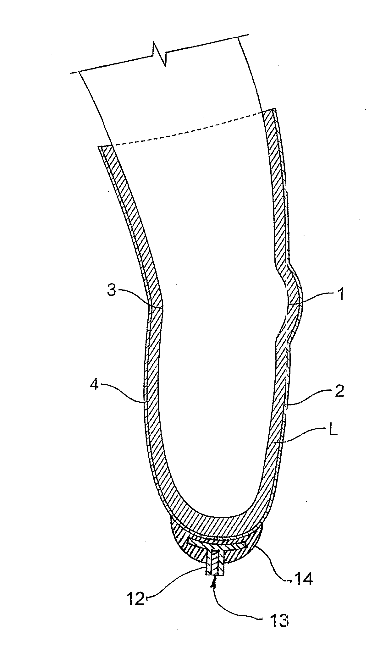
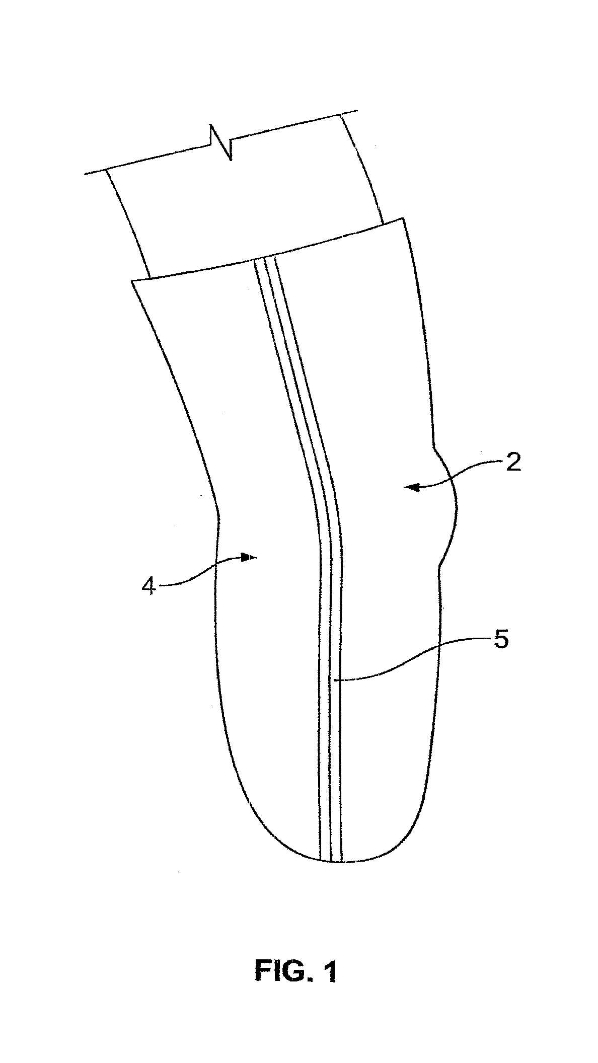
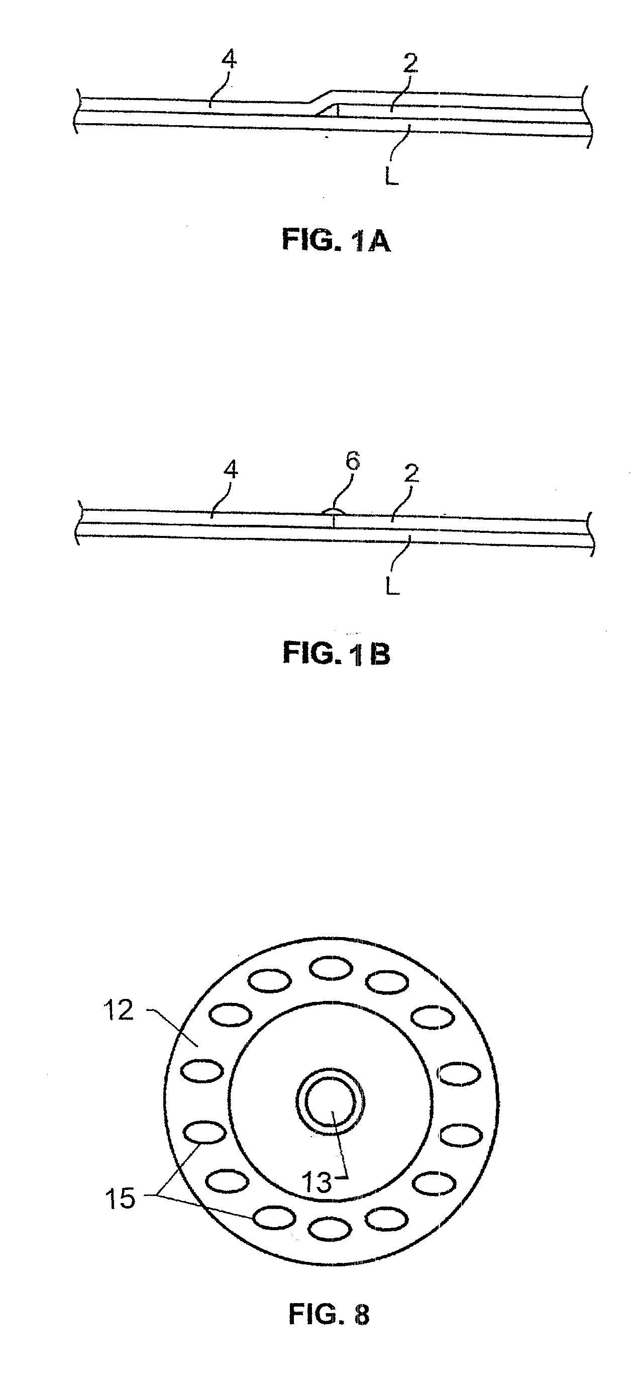
[0043]Referring to FIG. 4, the present invention is illustrated. FIG. 4 shows the inventive concept applied to an elastomeric sleeve (L) having anterior material (2) and posterior material (4) overlays do not extend to the stump end of the liner, and are laterally connected by a seam.

third embodiment

[0044]Referring to FIG. 5, the present invention is illustrated. FIG. 5 shows the inventive concept applied to an elastomeric sleeve (L) having anterior material (2) and posterior material (4) overlays do not extend to the stump end or to the open end of the liner, and are laterally connected by a seam.

fourth embodiment

[0045]Referring to FIG. 6, the present invention is illustrated. FIG. 6 shows the inventive concept with the addition of an insert member (7) molded into the distal end of the liner. The insert member (7) is made of metal or plastic, preferably brass, and includes a generally disc-shaped base (8) and a hollow cylindrical stem (9) extending therefrom. Base (8) is drawn flat, but could also be an umbrella-like configuration so that it conforms to the curvature of the distal end of the liner. The hollow stem (9) is internally threaded and adapted to threadedly receive a connector member (not shown) for locking the liner to the interior of a prosthetic socket. As illustrated in FIG. 6, the base (8) and part of the stem (9) is embedded in the gel of the liner and part of the stem is not embedded in the gel. The insert member (7) also includes two grommets (10) and (11). These grommets are made of metal or plastic, preferably brass, and have a central aperture that is slightly smaller tha...


PUM


Abstract

A prosthesis comprising an elastomeric locking liner sized and configured to surround a limb of a patient about a knee joint, the liner having an inner surface for facing the limb of the patient and an outer surface defining an anterior region and a posterior region which are demarcated by an imaginary plane extending midway between the front most portion and rear most portion of the limb along the length of the limb, wherein the anterior region has an anterior material secured thereto and the posterior region has a posterior material secured thereto and the anterior and posterior materials having equal transverse elongation, and the anterior material having a longitudinal elongation greater than the longitudinal elongation of said posterior material, whereby when said prosthesis is donned onto a limb of a patient over the knee and the limb is flexed about the knee, buckling of the prosthesis about the knee is substantially reduced or eliminated and wherein the distal end of the liner includes an insert member adapted to receive a connector for locking the liner to a prosthetic socket when worn on a residual limb of an amputee.

Description

[0001]This application is a continuation-in-part of U.S. Non-provisional application Ser. No. 12 / 454,299 filed on May 14, 2009, which claims priority to U.S. Provisional Application No. 61 / 053,036 filed on May 14, 2008, hereby incorporated by reference. This application is related to application Ser. No. 12 / 832,653 filed on Jul. 10, 2010.BACKGROUND[0002]A challenging aspect of treating those who have lost one or more limbs is the restoration of function to the remaining limb (residual limb). Such a restoration often means fitting the residual limb with one or more prostheses, or artificial limbs. A difficulty with artificial limbs is that they often do not physically interface well with the amputee. For instance, most prostheses comprise a cup into which the residual limb, protected with an elastomeric sheath or “liner,” is inserted and secured. Since the 1980's, prosthetic liners have generally been of polymeric materials. Such liners are described in U.S. Pat. Nos. 5,549,709; 6,64...

Claims


Application Information

Patent Timeline
IPC IPC(8): A61F2/80
CPCA61F2002/7818A61F2/7812
Inventor LAGHI, ALDO A.MCLOONE, KEVIN
Owner ALPS INTPROP MANAGEMENT
Why Eureka
Try Eureka