Aircraft systems and methods with active deceleration control

a technology of aircraft speed and control, applied in process and machine control, instruments, navigation instruments, etc., can solve the problems that conventional aircraft systems may find timing or other accuracy requirements challenging, and achieve enhanced control of aircraft, accurate time prediction, and accurate prediction.

Active Publication Date: 2011-11-03
HONEYWELL INT INC
View PDF2 Cites 30 Cited by
  • Summary
  • Abstract
  • Description
  • Claims
  • Application Information

AI Technical Summary

Benefits of technology

[0051]Accordingly, exemplary embodiments discussed herein provide a deceleration segment with a more accurate prediction, particularly a more accurate time prediction, of the end of the deceleration segment. For example, the aircraft system 100 may use an active, non-zero throttle setting to provide enhanced control the aircraft during the deceleration segment. The deceleration segments may be more consistent and provide improved results in descent path tracking and speed profile execution. Additionally, the aircraft system 100 may repeatedly recalculate the calculated path during the deceleration segment. The aircraft system 100 may also enable more accurate flying of the calculated speed profile by incorporating a lead factor into the throttle settings.

Problems solved by technology

Given the already complex considerations of flight planning, as well as the uncertainty associated with implementing such planning, conventional aircraft systems may find the timing or other accuracy requirements to be challenging.

Method used


Image

  • Aircraft systems and methods with active deceleration control
  • Aircraft systems and methods with active deceleration control
  • Aircraft systems and methods with active deceleration control

Examples


Embodiment Construction

[0015]The following detailed description is merely exemplary in nature and is not intended to limit the invention or the application and uses of the invention. As used herein, the word “exemplary” means “serving as an example, instance, or illustration.” Thus, any embodiment described herein as “exemplary” is not necessarily to be construed as preferred or advantageous over other embodiments. All of the embodiments described herein are exemplary embodiments provided to enable persons skilled in the art to make or use the invention and not to limit the scope of the invention which is defined by the claims. Furthermore, there is no intention to be bound by any expressed or implied theory presented in the preceding technical field, background, brief summary, or the following detailed description.

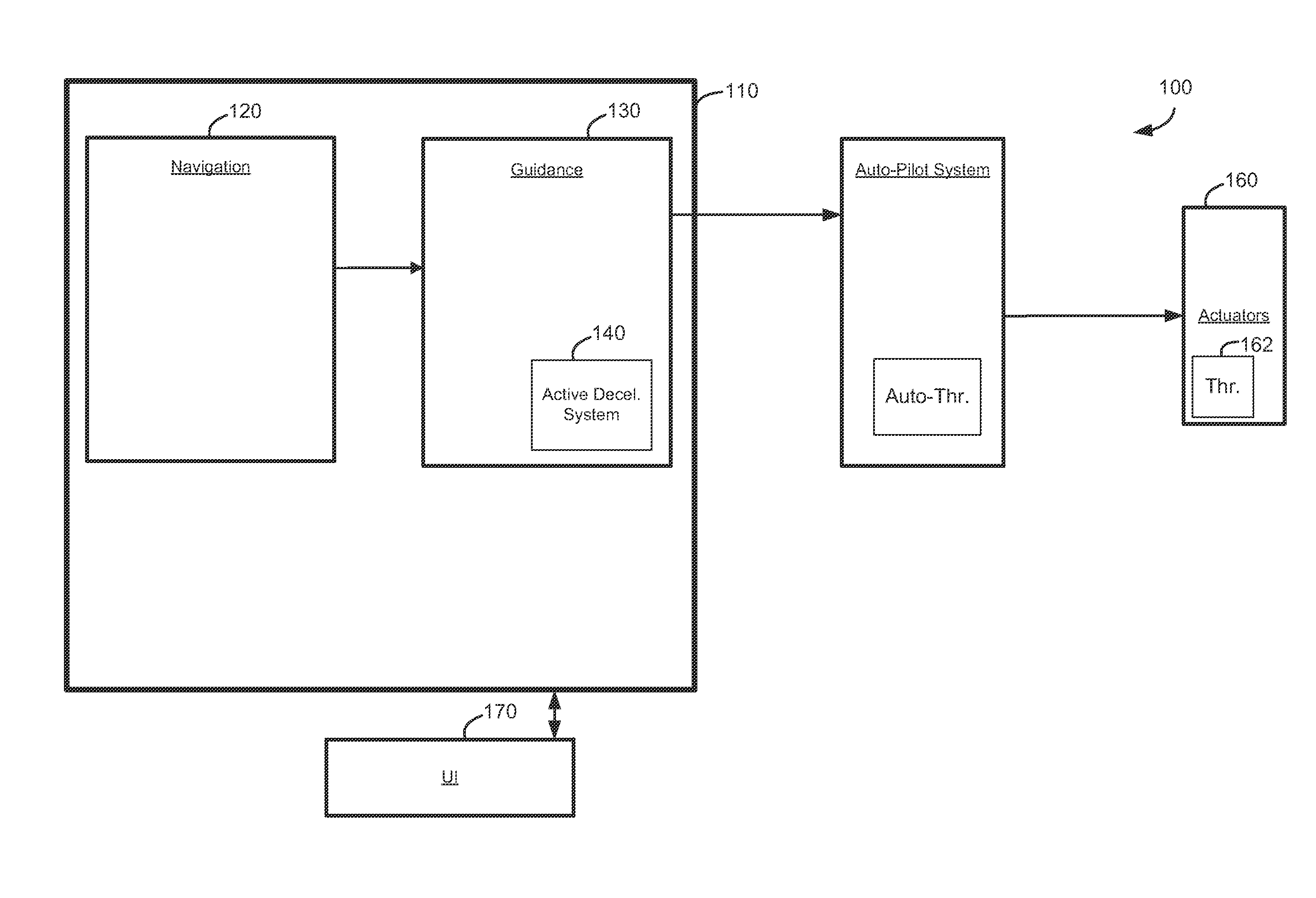
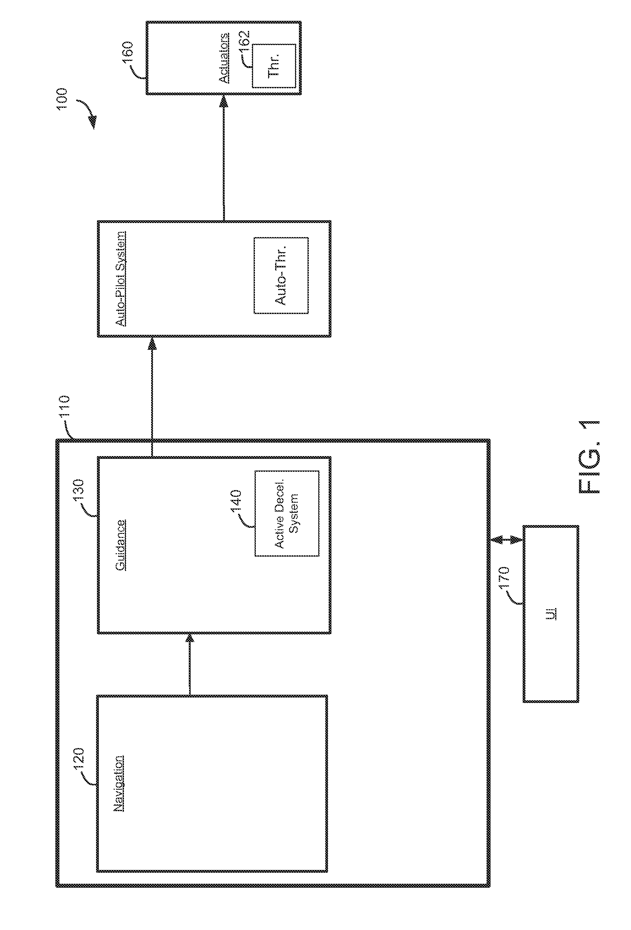
[0016]Broadly, exemplary embodiments discussed herein include aircraft systems and methods for controlling an aircraft during flight. Particularly, the system and methods are applicable to an a...


PUM


Abstract

A system is provided for controlling the speed of an aircraft during a deceleration segment between a first state associated with a first speed and a first time and a second state associated with a second speed and a second time. The system includes a navigation system configured to determine the first state; a guidance system configured to determine the second state; and an active deceleration system coupled to the navigation system and the guidance system and configured to construct the deceleration segment between the first state and the second state with at least one intermediate speed between the first speed and the second speed.

Description

PRIORITY CLAIM[0001]This application claims the benefit of U.S. Provisional Application No. 61 / 329,988, filed Apr. 30, 2010, the disclosure of which is hereby incorporated by reference.TECHNICAL FIELD[0002]The present invention generally relates to aircraft systems and methods, and more particularly relates to the systems and methods for controlling the speed of an aircraft.BACKGROUND[0003]Commercial aircraft make extensive use of systems to plan and execute flights, control the aircraft, and manage a number of other aircraft operations. For example, such systems may include a flight management system (FMS) that generates flight plans with lateral segments and vertical segments to a destination. The flight plans may include details about the appropriate speeds, altitudes, and location during ascent, cruising, and descent modes of a flight. Particularly, the flight plans require the aircraft to be at a certain speed and altitude at a specified lateral position, and the FMS determines...

Claims


Application Information

Patent Timeline
Patent Type & Authority Applications(United States)
IPC IPC(8): B64C19/00B64C19/02G06F19/00
CPCG05D1/0607G08G5/0065G08G5/003
Inventor SVOBODA, JIRIJACKSON, MIKEPOLANSKY, MICHALPARICAUD, ERWAN
Owner HONEYWELL INT INC
Why Eureka
Try Eureka